Temperature sensor for power supply

a temperature sensor and power supply technology, applied in the field of power supplies, can solve the problems of further damage to the power supply, the user of the power supply, the power source, etc., and achieve the effect of reducing the power level of the power supply and reducing the overheating of the power supply

Inactive Publication Date: 2008-08-05
RRC POWER SOLUTIONS
View PDF32 Cites 83 Cited by
  • Summary
  • Abstract
  • Description
  • Claims
  • Application Information

AI Technical Summary

Benefits of technology

[0009]A temperature sensor, such as a thermistor, senses the temperature of a power supply connector, or other portion of the power supply, such as an electrical cable. This sensed temperature may then be used to determine, such as by a microcontroller or other power control module, if the output power should be reduced or switched off in order to avoid overheating of a cigarette lighter. This may prevent damage to the plastic components of the power supply, the cigarette lighter receptacle, and the electronic device coupled to the power supply.
[0011]In another embodiment, a method of reducing overheating of a power supply configured to receive a power signal from a vehicle through a cigarette lighter receptacle comprises sensing a temperature of at least a portion of the power supply, determining if the sensed temperature is greater than a predetermined threshold; and reducing a power level of the power supply in response to determining that the sensed temperature is greater than a predetermined threshold temperature.
[0013]In another embodiment, a system for reducing overheating of a power supply configured to receive a power signal from a cigarette lighter receptacle in a vehicle comprises means for sensing a temperature of at least a portion of the power supply, means for determining if the sensed temperature is greater than a predetermined threshold, and means for reducing a power level of the power supply in response to determining that the sensed temperature is greater than a predetermined threshold temperature.

Problems solved by technology

In the event that short circuits or other faults occur in one or more of the electrical cables, the heat generated by the short circuit may melt the plastic cable housing, potentially causing further damage to the cable, the power, supply, the power source, the electronic device, and the user of the power supply.
However, current power supplies do not monitor the temperature of anything outside the main power supply housing and such an overheating condition may not be recognized.
However, some automobiles are not in compliance with the standardized vehicle receptacle specifications.
Thus, power supplies having standardized vehicle connectors may not properly engage with these out of specification vehicle receptacles.
In addition, even a vehicle receptacle designed in compliance with standardized vehicle receptacle specification may have an incomplete connection with a power supply connector.
If a vehicle connector is incompletely contacting the vehicle receptacle, there is a possibility for heat generation in the vehicle connector and melting or other damaging of components in the connector.

Method used


Image

  • Temperature sensor for power supply
  • Temperature sensor for power supply
  • Temperature sensor for power supply

Examples


Embodiment Construction

[0018]The following is a detailed description of embodiments of the invention. However, the invention can be embodied in a multitude of different ways as defined by the claims. The invention is more general than the embodiments that are explicitly described, and accordingly, is not limited by the specific embodiments.

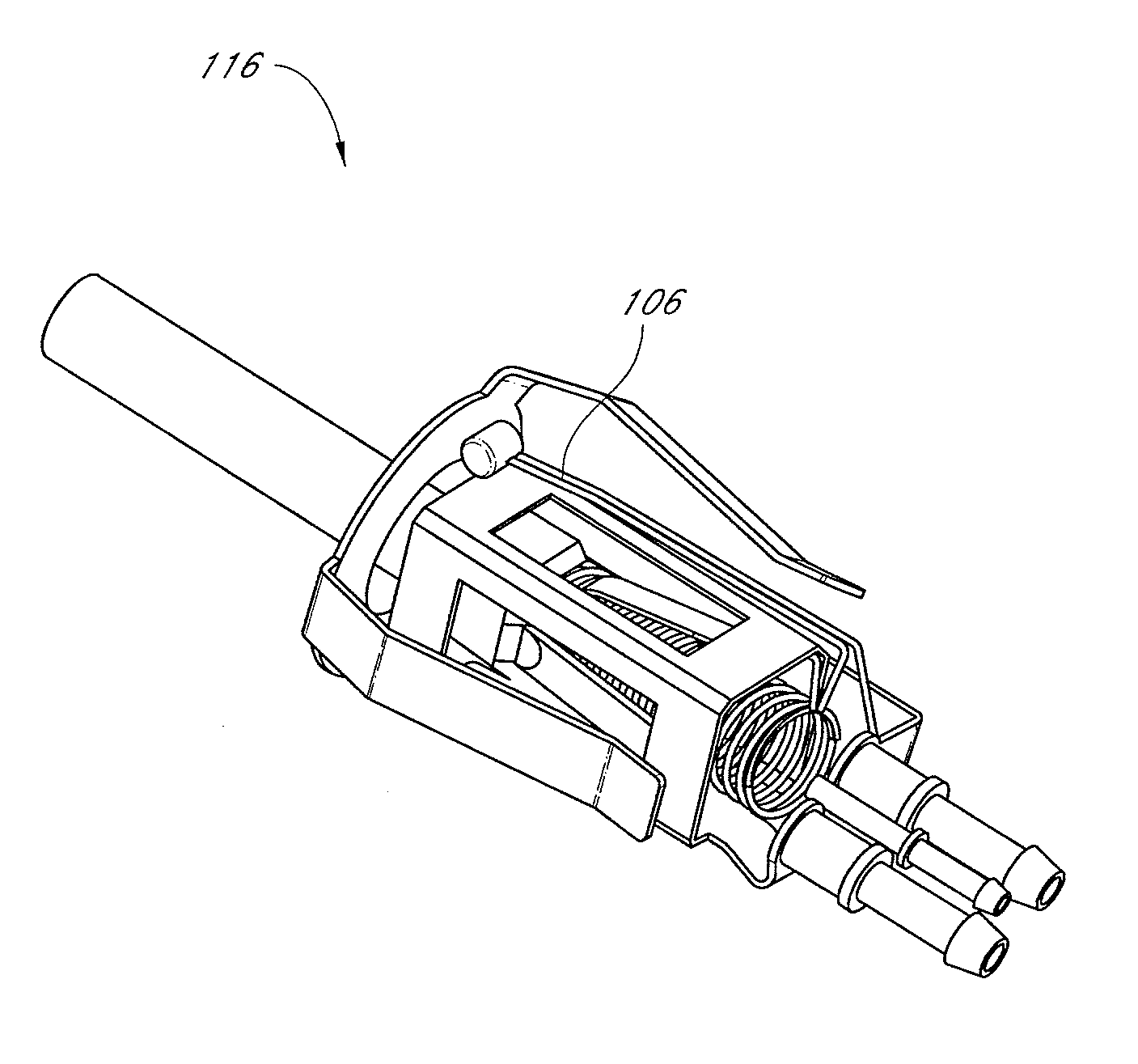
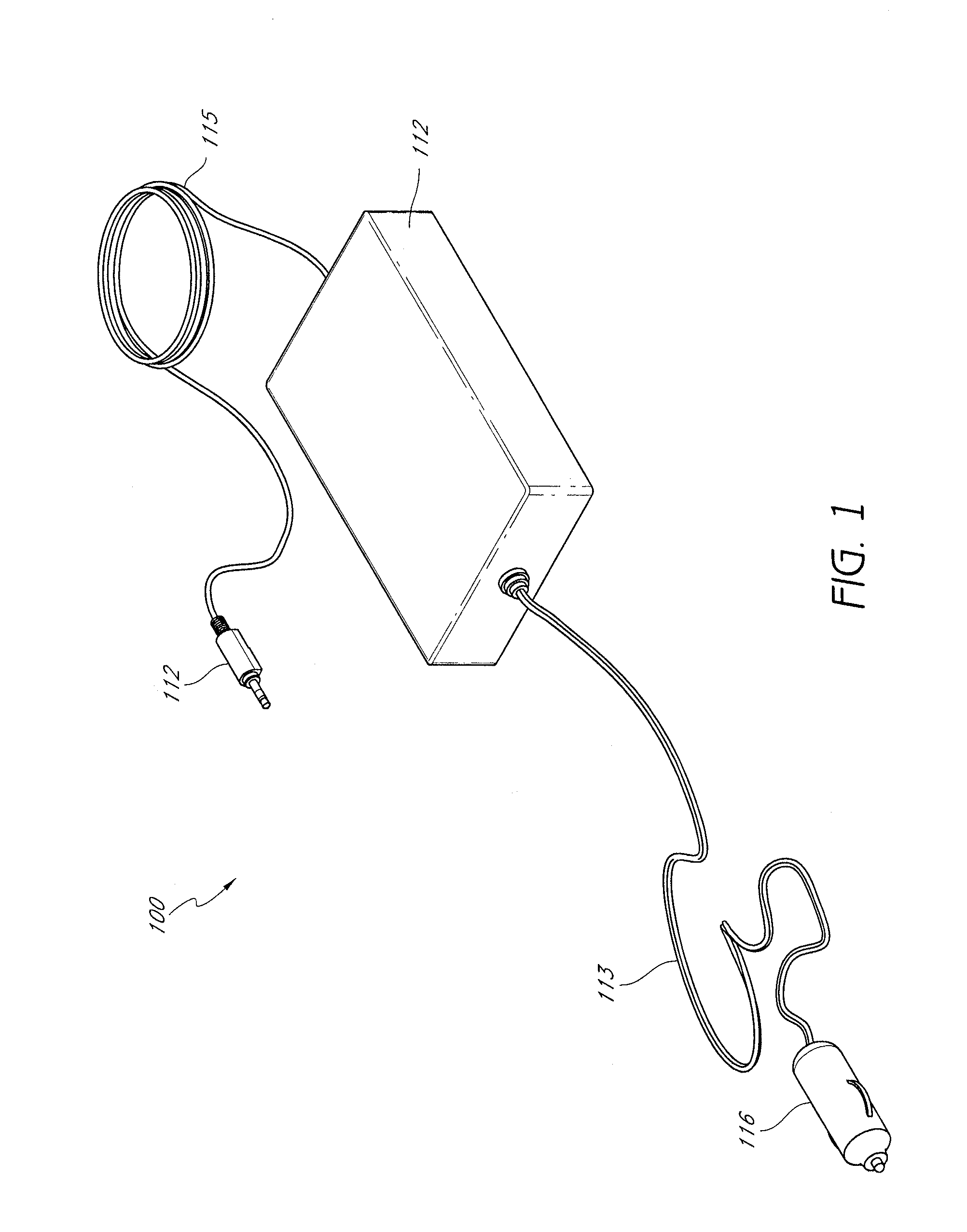
[0019]FIG. 1 is an illustration of a power supply 100, including a power supply housing 112, a power source connector 116, an electronic device connector 114, and electrical connection lines 113 and 115 coupling the power source and the electronic device, respectively, to the power supply 112. In operation, the power source connector 116 is coupled to a power source through a connector, such as a cigarette lighter receptacle in a vehicle (referred to herein as a “vehicle receptacle”) or an in-seat power receptacle in an aircraft (referred to herein as an “air receptacle”). The power is delivered to the power supply housing 112, which includes power conversion and / or tra...


PUM


Abstract

A temperature sensor, such as a thermistor, senses the temperature inside a power source connector, or other portion, of a power supply. This sensed temperature may then be used to determine if the output power should be reduced or switched off in order to avoid overheating of the connector, or other portion of the power supply. Overheating of the power supply may occur, for example, if contact between the connector and a cigarette lighter power receptacle is incomplete. A microcontroller may be used to monitor the temperature sensed by the temperature sensor and reduce or disable the power supply if the temperature is above a threshold temperate. Accordingly, heat damage to the plastic components of the power supply, the cigarette lighter receptacle, may be reduced.

Description

RELATED APPLICATIONS[0001]This application is related to, and hereby incorporates by reference the entire disclosure of each of the following commonly owned U.S. patent applications, each filed on even date herewith: (1) U.S. patent application Ser. No. 10 / 984,552, titled “Microcontroller Controlled Power Supply,” (2) U.S. patent application Ser. No. 10 / 984,695, titled “Power Supply Configured to Detect a Power Source,” and (3) U.S. patent application Ser. No. 10 / 984,550, titled “Power Supply Connector.”BACKGROUND OF THE INVENTION[0002]1. Field of the Invention[0003]This invention relates to power supplies and, more specifically, to power supplies configured to monitor temperature of components external to a power supply housing.[0004]2. Description of the Related Art[0005]In order to power many electronic devices, such as household appliances, stereo components, and computing devices, for example, those devices typically include a power supply configured for coupling with an extern...

Claims


Application Information

Patent Timeline
Patent Type & Authority Patents(United States)
IPC IPC(8): H05B1/02
CPCH02H5/042
Inventor WAMBSGANSS, PETERHACKETT, GARETH J.
Owner RRC POWER SOLUTIONS
Why Eureka
Try Eureka