Photovoltaic device and method for encapsulating

a photovoltaic device and photovoltaic technology, applied in the direction of semiconductor devices, basic electric elements, electrical apparatus, etc., can solve the problems of macroscopic cracking of the substrate, thermal stress, thermal stress,

Inactive Publication Date: 2009-04-09
SAINT-GOBAIN GLASS FRANCE
View PDF16 Cites 55 Cited by
  • Summary
  • Abstract
  • Description
  • Claims
  • Application Information

AI Technical Summary

Benefits of technology

[0024]The invention further provides the use of a cover plate provided with a transparent area and an opaque and UV absorbing area adjacent the transparent area for encapsulating a photovoltaic device comprising a thin-film photovoltaic layer arranged on a substrate, and for protecting UV degradable material, in particular polymeric material, more in particular polymeric sealant material, present adjacent the photovoltaic layer from UV induced degradation.
[0025]The invention moreover provides the use of a cover plate provided with a transparent area and an opaque area adjacent the transparent area for encapsulating a photovoltaic device comprising a thin-film photovoltaic layer arranged on a substrate that is larger than the photovoltaic layer, and for protecting the encapsulated photovoltaic device from thermal stress during due to light irradiation.

Problems solved by technology

A particular problem that can be handled in this way is thermal stress.
Under irradiation of sunlight, therefore, the photovoltaic device area and the remaining area are differently heated, leading to thermal stress.
This is particularly problematic in a border area of a fragile substrate.
Thermal stress in the border area can result in macroscopic cracking of the substrate.
Many polymers degrade over time, and degradation is often driven by light and in particular UV irradiation.

Method used


Image

  • Photovoltaic device and method for encapsulating
  • Photovoltaic device and method for encapsulating
  • Photovoltaic device and method for encapsulating

Examples


second embodiment

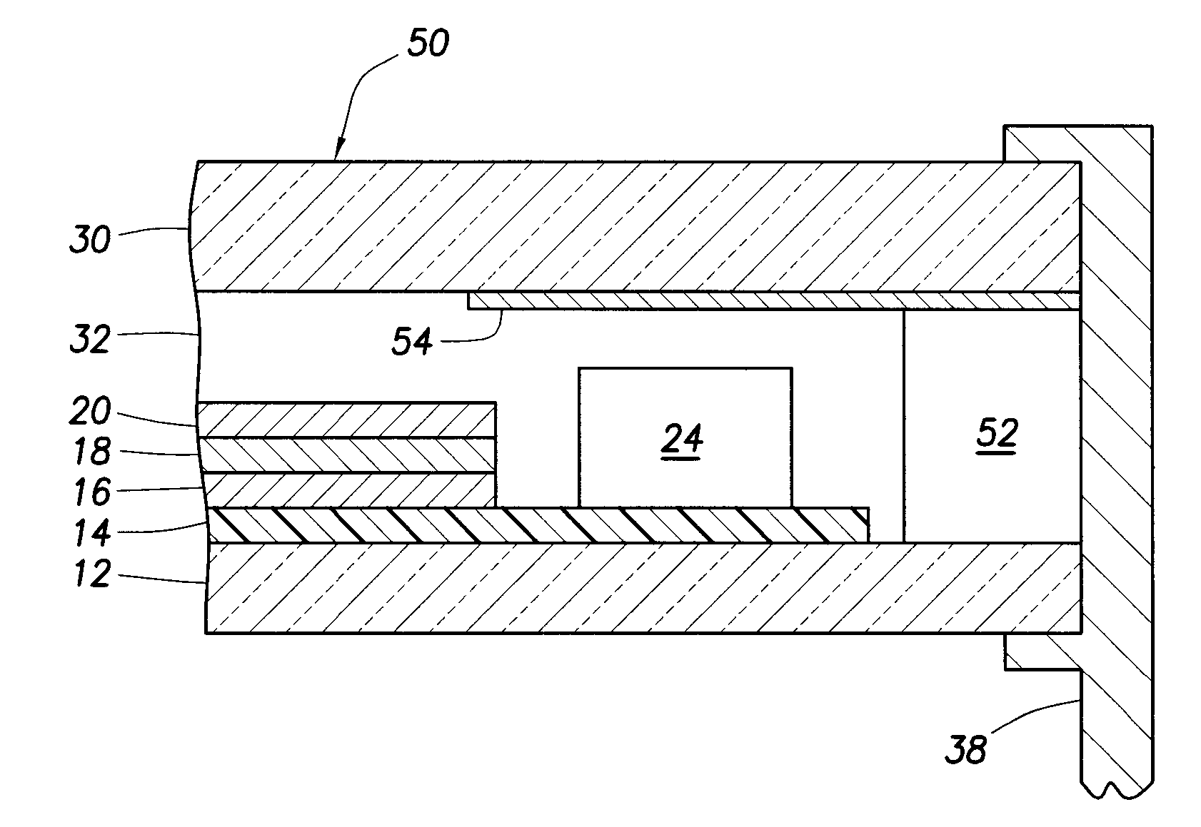
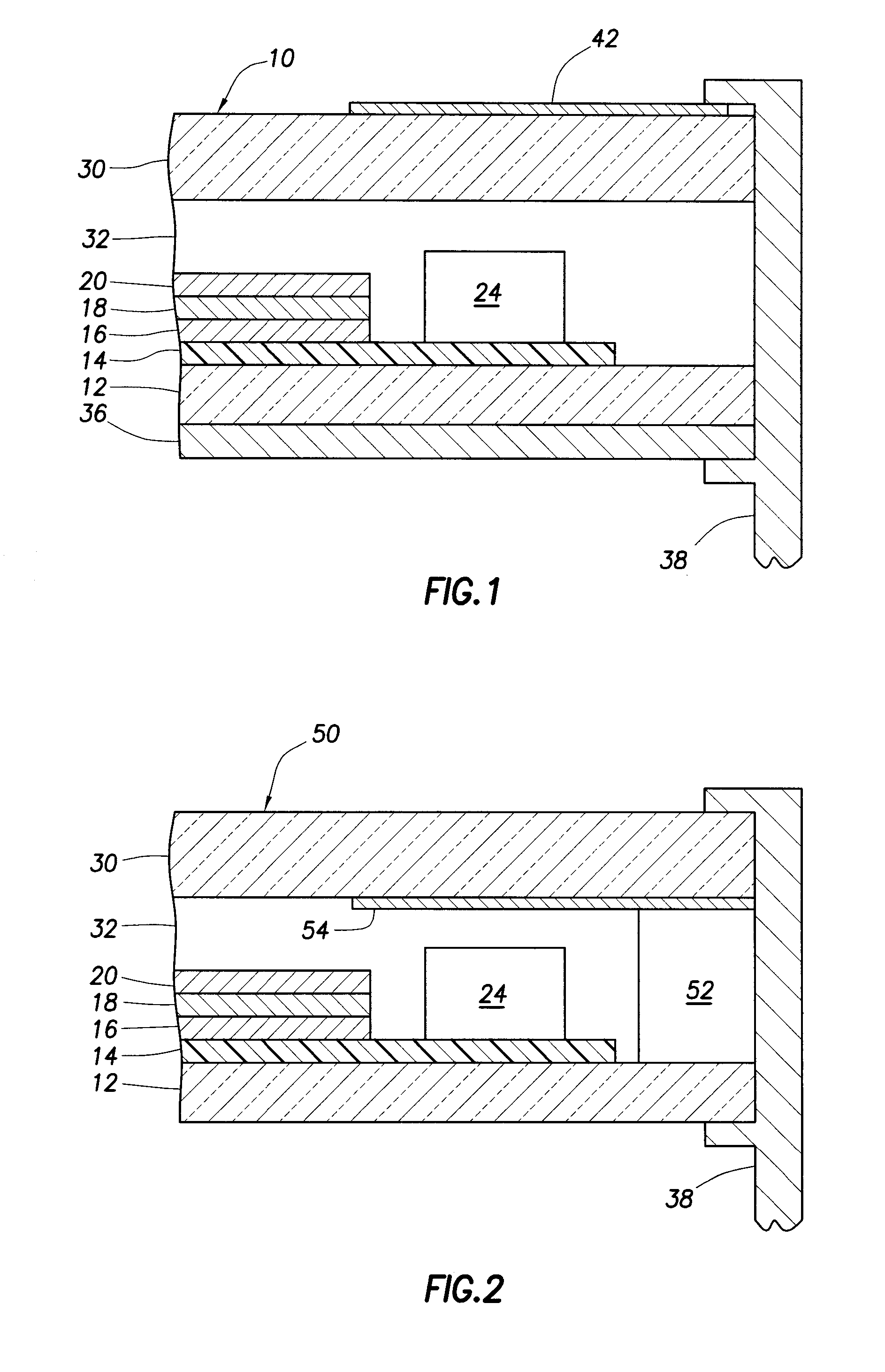
[0048]Reference is now made to FIG. 2, showing a photovoltaic device 50 according to the invention. The devices are largely similar same reference numerals as in FIG. 1 are used to refer to the same or similar parts, and we refer to the discussion thereof above. It is sufficient to discuss the differences with the embodiment of FIG. 1. Along the edges of the photovoltaic device a polymeric sealant material in the form of a tape 52 is arranged. The edge seal may preferably comprise a moisture repellent material and / or a desiccant. Examples of suitable edge seal materials include butyl rubber, urethane and polyurethane materials, polyisobutylene materials, epoxide materials, polysulfamide materials; and cyanoacrylates. Such edge sealants may be applied in the form of a tape or strip prior to bringing the backside layer and the light-facing layer together.

[0049]The protecting layer 36 is not present on the rear side of the substrate.

[0050]The opaque area 54 is arranged as a coating on ...

third embodiment

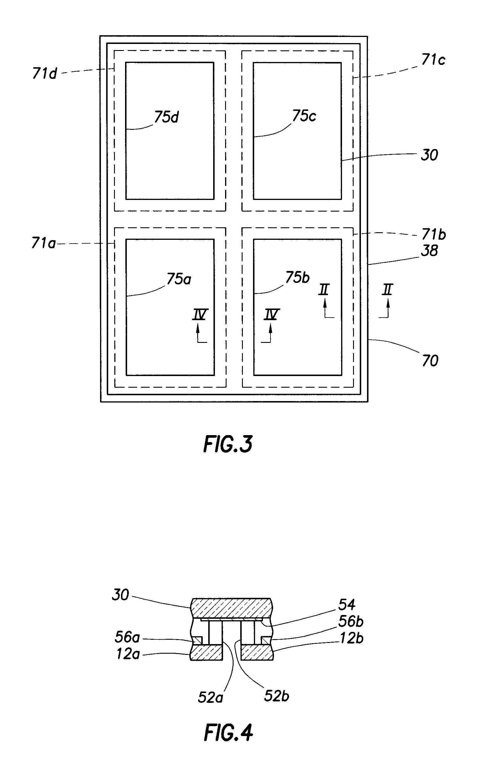
[0051]Reference is made to FIGS. 3 and 4, showing schematically a photovoltaic device 70 according to the invention, in top view and in a cross-section along line IV-IV. FIG. 3 shows a solar module formed of four solar cells 71a,b,c,d underneath a common cover glass 30 and in a common frame 38. The module is largely similar to the device 50 of FIG. 2, in fact FIG. 2 can be regarded as a cross-section along line II-II. In a module formed of a plurality of solar cells there can however be regions other than the circumference where the invention can be applied. In the cross-section of FIG. 4 it is shown, that opaque area 54 can likewise be arranged in a central part of the photovoltaic device. The solid rectangles 75a,b,c,d in FIG. 3 indicate the transparent area of the cover, and the remaining area of the cover glass that can receive light (such as outside the frame) is suitably all opaque. It shall be clear that FIGS. 3 and 4 are not to scale, the fraction of opaque area is exaggerat...


PUM


Abstract

A photovoltaic device comprising a photovoltaic layer between a substrate and a cover plate, which cover plate is transparent in an area above the photovoltaic layer, wherein the cover plate overlaps the photovoltaic layer, and wherein the cover, in an area adjacent to the photovoltaic layer, is opaque; a method of encapsulating a photovoltaic device with such a cover plate, and the use of such a cover plate for encapsulating a photovoltaic device, for protecting polymeric sealant material present adjacent the photovoltaic layer from light induced degradation and/or for protecting the encapsulated photovoltaic device from thermal stress during due to light irradiation.

Description

FIELD OF THE INVENTION[0001]The present invention relates to a photovoltaic device, to a method of encapsulating a photovoltaic device, and to the use of a cover for encapsulating a photovoltaic device.BACKGROUND OF THE INVENTION[0002]Solar cells are typically formed of a photovoltaic layer arranged on a substrate, and encapsulated for protection against environmental influences. On the light-receiving side a cover is provided, typically of a transparent material, in particular hardened glass is often used.[0003]Thin-film solar cells are typically arranged on a glass substrate. In thin-film solar cells the photovoltaic layer is a thin film comprised of one or more thin layers forming a photoactive pn-junction, and including necessary electrodes. A particular thin film solar cell is a so-called chalkopyrite or I-III-VI solar cells. Another thin-film solar cell is an amorphous silicon solar cell.[0004]The photovoltaic layer of a solar cell does not normally cover the entire substrate ...

Claims


Application Information

Patent Timeline
Patent Type & Authority Applications(United States)
IPC IPC(8): H01L31/00
CPCH01L31/048Y02E10/541H01L31/0749H01L31/0488
Inventor CALWER, HERMANNPROBST, VOLKERWIETING, ROBERT D.
Owner SAINT-GOBAIN GLASS FRANCE
Why Eureka
Try Eureka