Optical signal transmission apparatus and optical signal transmission method

a technology of optical signal transmission and optical signal, which is applied in the direction of transmission monitoring, electromagnetic transceivers, selective content distribution, etc., can solve the problem that the optical main signal status becomes non-receiving, and achieve the effect of improving safety and positively preventing the leakage of laser ligh

Inactive Publication Date: 2006-01-12
FUJIFILM BUSINESS INNOVATION CORP
View PDF10 Cites 59 Cited by
  • Summary
  • Abstract
  • Description
  • Claims
  • Application Information

AI Technical Summary

Benefits of technology

[0016] Here, when the optical sub-signal is not being received, or when the reception status of the optical main-signal indicates non-receiving, the output of the optical main-signal is stopped by the control component. In other words, the output of the optical main-signal is stopped when the optical sub-signal changes to not being received, and the optical main-signal status becomes non-receiving, due to such causes as the optical cable being non-connecting or damaged. Thereby, leakage of the optical main-signal from the optical cable can be positively prevented. For example, when a laser light source is used as the light source of the optical main-signal, as described above, leakage of the laser light can be prevented.
[0017] Further, under one or other (or both) of two conditions (the optical sub-signal not being received or the optical main-signal status being non-receiving), the output of the optical main-signal is stopped. Thus if a circuit or the like for detecting one of the conditions fails, the circuit for detecting the other is capable of stopping the output of the optical main-signal. This allows safety to be improved with leakage of the laser light being reliably prevented.
[0019] As described above, the present invention provides an effect that, when the optical sub-signal is not being received, or when the reception status [of the optical main-signal] is non-receiving, the output of the optical main-signal is stopped. Hence leakage of the laser light can be positively prevented and thus safety can be improved.

Problems solved by technology

In other words, the output of the optical main-signal is stopped when the optical sub-signal changes to not being received, and the optical main-signal status becomes non-receiving, due to such causes as the optical cable being non-connecting or damaged.

Method used


Image

  • Optical signal transmission apparatus and optical signal transmission method
  • Optical signal transmission apparatus and optical signal transmission method
  • Optical signal transmission apparatus and optical signal transmission method

Examples


Embodiment Construction

[0030] Hereinbelow, an example of an embodiment of the present invention will be explained in detail with reference to the drawings.

[0031] (Entire Configuration)

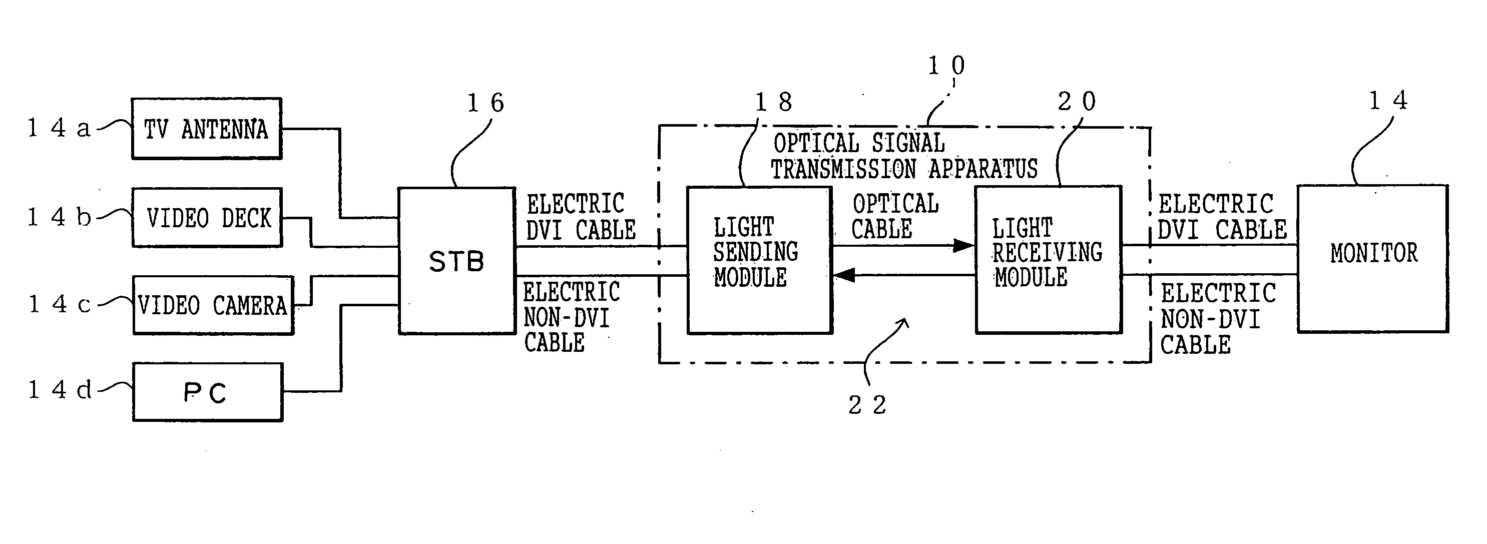
[0032] As shown in FIG. 1, a video signal transmission system according to the present embodiment is a system that selects a video / image signal from various media to display it on a monitor 14.

[0033] The various media are, for example, a TV antenna 14a, a video deck 14b, a video camera 14c, a personal computer (PC) 14d, and the like. The system can be applied to television signals obtained from the antenna 14a, video signals obtained from the video deck 14b, video camera 14c, and the like, image signals obtained from the PC 14d, and the like.

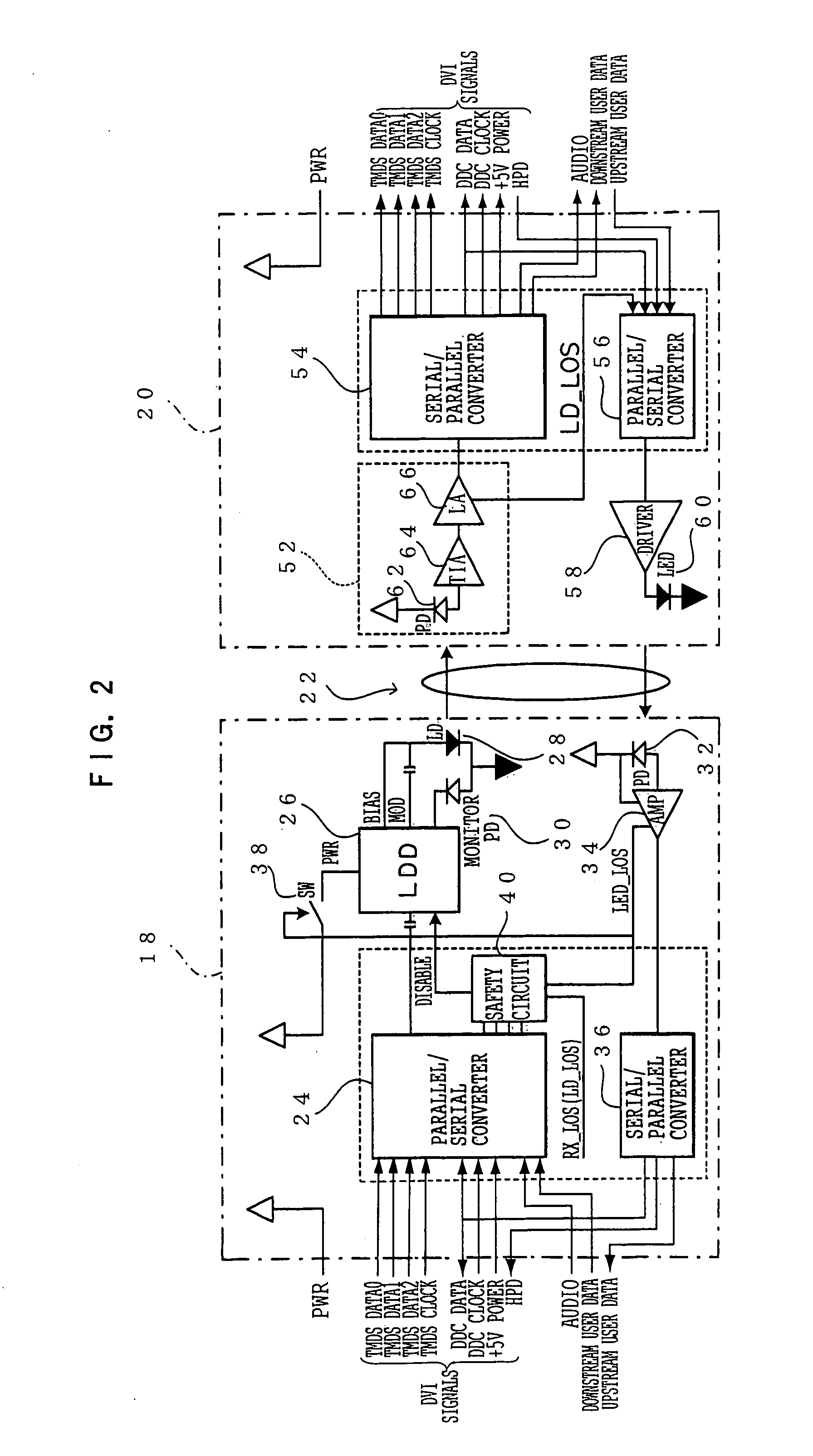
[0034] A video / image signal from each of the various media is outputted as a video signal, corresponding to each of the various interfaces, by a device called a set top box (STB) 16. This STB 16 selects a video / image signal and outputs it as a video signal, via an optical signal tran...


PUM


Abstract

The present invention provides an optical signal transmission apparatus for carrying out bi-directional light transmission. The optical signal transmission apparatus includes: a light sending module, for sending an optical main-signal having at least one data width, and receiving an optical sub-signal including a control signal; a light receiving module for receiving the optical main-signal and sending the optical sub-signal; and an optical cable for connecting between the light sending module and the light receiving module, wherein the light sending module comprises a control component which controls the output of the optical main-signal such that the output of the optical main-signal is stopped, when the optical sub-signal, which includes as data the reception status of the optical main-signal, is not being received, or when the reception status of the optical main-signal is indicating non-receiving.

Description

CROSS-REFERENCE TO RELATED APPLICATION [0001] This application claims priority under 35USC 119 from Japanese Patent Application Nos. 2004-199225 and 2005-14005, the disclosures of which are incorporated by reference herein. BACKGROUND OF THE INVENTION [0002] 1. Field of the Invention [0003] The present invention relates to an optical signal transmission apparatus and an optical signal transmission method, and more particularly to an optical signal transmission apparatus and an optical signal transmission method which use optical signals. [0004] 2. Description of the Related Art [0005] With liquid crystal panels and plasma displays being provided with higher resolutions, it is desired that large-volume video signals from the host be transmitted whilst being kept in a digital format. For example, the DVI (Digital Visual Interface) standard, which has been defined by DDWG (Digital Display Working Group), an industry organization, is a standard for differential signaling called TMDS (Tr...

Claims


Application Information

Patent Timeline
Patent Type & Authority Applications(United States)
IPC IPC(8): H04B10/12H04B10/07H04B10/077H04B10/40H04B10/50H04B10/60H04B10/80H04N7/22H04N21/61H04N21/647
CPCH04B10/00
Inventor SAKAI, KAZUHIROSATO, YOSHIHIDEKIJIMA, MASARU
Owner FUJIFILM BUSINESS INNOVATION CORP
Why Eureka
Try Eureka