
Cellular radio communications system

a radio communication system and cellular technology, applied in the field of cellular radio communication systems, can solve the problems of low data transmission rate, low performance of wireless access communication systems, and waste of maximum symbol rate bandwidth, so as to improve the use of bandwidth, increase the level of forward error correction coding, and reduce the power of transmission links

Inactive Publication Date: 2005-09-20
MICROSOFT TECH LICENSING LLC
View PDF4 Cites 81 Cited by
  • Summary
  • Abstract
  • Description
  • Claims
  • Application Information

AI Technical Summary

Benefits of technology

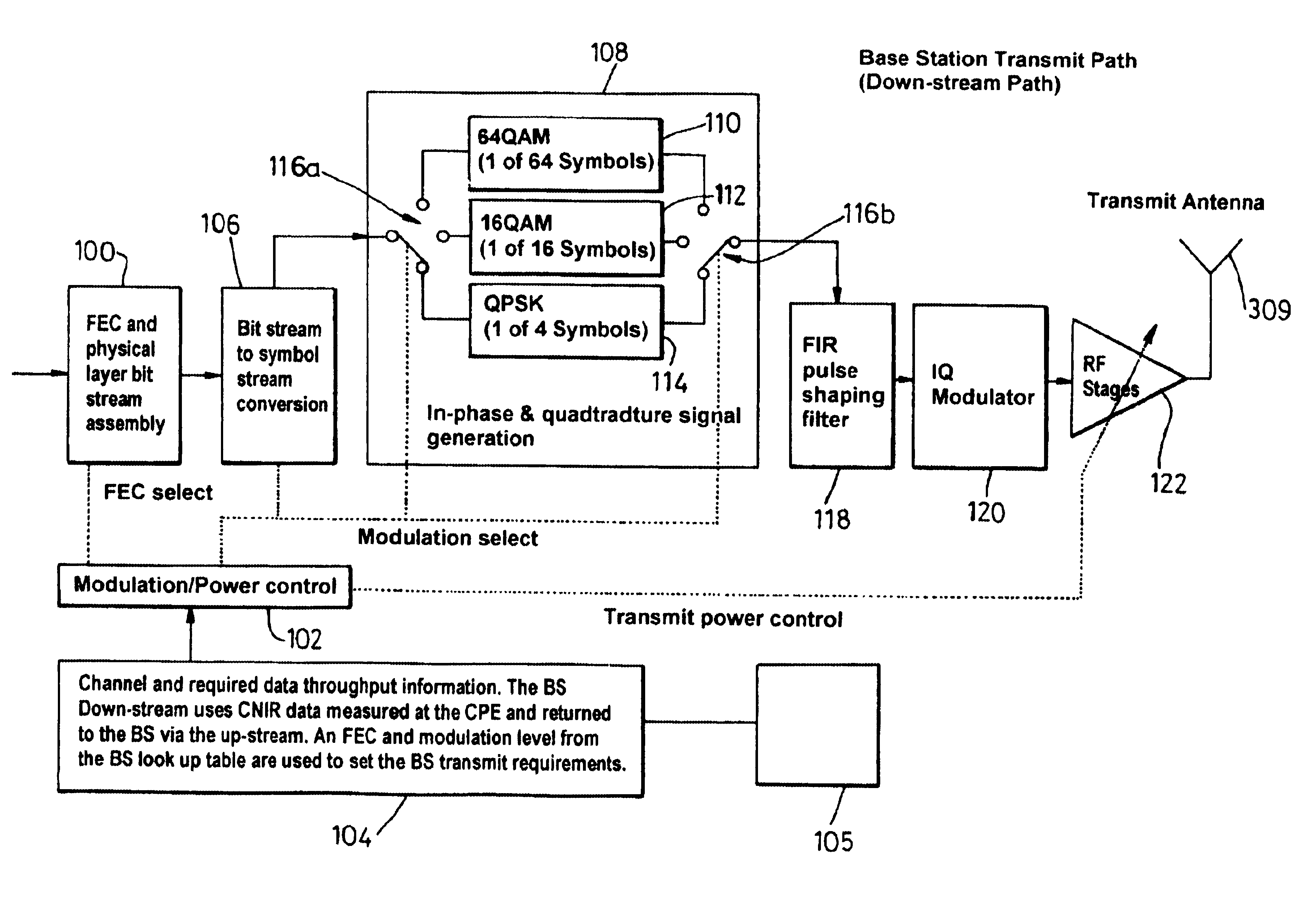
[0015]Preferably the system comprises means for adjusting the power of the transmission links dependent on the level of traffic over the transmission links while maintaining the predetermined bit error rate. This may be achieved by increasing the level of forward error correction coding allocated to the transmission links so as to use all the bandwidth of the transmission links and by reducing the power of the transmission links dependent on the change in the level of forward error correction coding to maintain the predetermined bit error rate. Thus, if a particular cell comprising the base station and the end user terminals does not need to utilise the total bandwidth of its transmission links, the level of coding can be increased to use up the remaining bandwidth which enables the power of the transmission links to be reduced while still achieving the required bit error rate. The whole bandwidth allocated to the cell is used but at a lower power level. The fact that the cell is transmitting at a lower power level means that it is generating less interference in neighbouring cells. This enables the neighbouring cells to support a higher data rate if they need to. Thus, those cells that do not require maximum data throughput can effectively release bandwidth to neighbouring cells by using the minimum level of power associated with achieving the required bit error rate.
[0030]According to a preferred embodiment of the present invention means are provided for storing a default modulation scheme suitable for the or each transmission link in poor environmental conditions for use when a call is initiated over the transmission link. Thus, a call may be initiated successfully at any time despite the prevailing environmental conditions.
[0032]Preferably the present invention utilises a power control scheme for improving the use of bandwidth across a geographical area covered by a mosaic of cells by using means for adjusting the power of the transmission links dependent on the level of traffic over the transmission links while maintaining the predetermined bit error rate. Preferably, means are provided for increasing the level of forward error correction coding allocated to the transmission links so as to use the bandwidth of the transmission links and means are provided for reducing the power of the transmission links dependent on the increase in the level of forward error correction coding to maintain the predetermined bit error rate.

Problems solved by technology

The performance of wireless access communication systems is prone to dynamic degradation, ie. time variant degradation, due to changing environmental conditions.
However, designing such systems for worst case environmental conditions in this way results in low rates of data transmission.
Thus, when the optimum symbol rate is less than this maximum symbol rate bandwidth will be wasted.
Accordingly, the system described in U.S. Pat. No. 5,940,439 is not efficient in its use of bandwidth.
Also, U.S. Pat. No. 5,940,439 does not provide an algorithm for determining the three variables.
In poor transmission conditions, more data will have to be se-sent and so data rates will be low.
However, this method has a degree of transmission delay inherent within it which may not be appropriate for all multimedia services.
It is also inefficient in terms of the amount of uplink or downlink resource used for services requiring a low bit error rate.

Method used


Image

  • Cellular radio communications system
  • Cellular radio communications system
  • Cellular radio communications system

Examples


Embodiment Construction

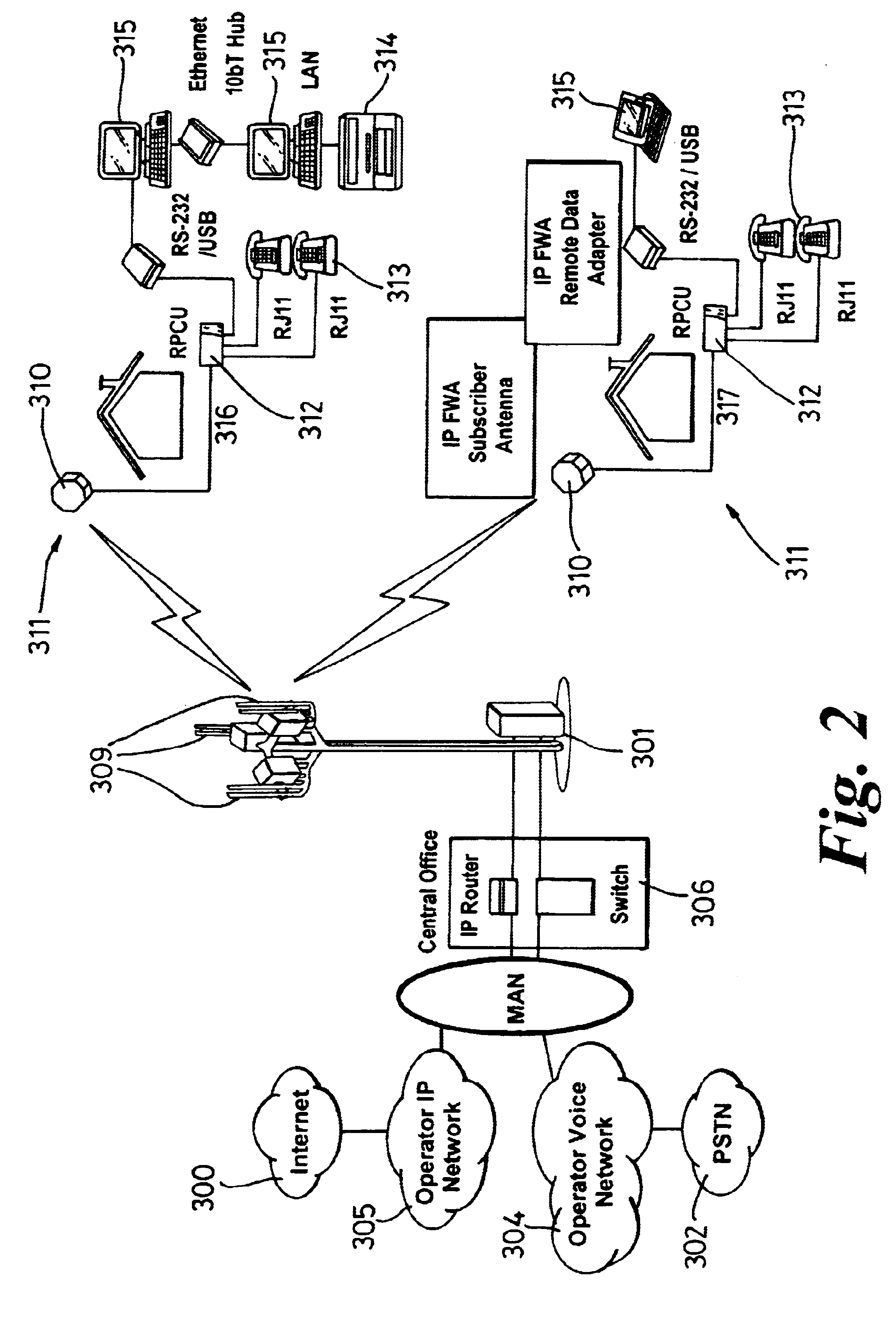
[0072]FIG. 2 shows a fixed wireless access architecture suitable for use in a cellular radio communication system according to the present invention. The architecture comprises a fixed wireless access base station (301) which can transmit radio frequency signals to a plurality of CPEs (Customer Premise Equipments) (311) within a localised area or cell. The base station has an array of antennas (309) for transmitting signals to and receiving signals from antennas (310) which form part of the CPEs (311). The antennas (310) located at a subscriber's premises and the base station antennas (309) are generally located in a raised position at some distance from the ground in order to reduce the effect of obstacles in the transmission paths between the base station and the CPEs. In this way a line of sight (LOS) or near line of sight (NLOS) transmission link can be achieved between the base station and each CPE within the cell. The CPE antennas (310) are each connected to associated remote ...


PUM


Abstract

A cellular radio communication system for transmitting blocks of data over transmission links in which the quality of the transmission links are monitored. The system comprises a data storage means for storing sets of modulation scheme and forward error correction coding level pairs to give an optimum data rate at a predetermined bit error rate and a predetermined symbol rate for different quality transmission links. The database is interrogated and a modulation scheme and forward error correction coding level pair is allocated and applied to the blocks of data transmitted over a transmission link dependent on the monitored quality of the transmission link.

Description

FIELD OF INVENTION[0001]The present invention relates to a cellular radio communication system. In particular the present invention relates to a broadband wireless access system suitable for the delivery of multi-media services.BACKGROUND OF INVENTION[0002]There is a growing demand for broadband wireless access systems which can deliver the high data rates required for the provision of multi-media services. Such wireless access systems operate within licensed frequency bands. Accordingly, these systems are continually developing to carry more data across the limited frequency band allocated to them. Pressure for this development is two fold. Firstly, there is increased demand for multi-media services from subscribers to the system. Secondly, revenue for the network operator will increase as billing is calculated on a per byte of information delivered basis as opposed to on a timed basis.[0003]The performance of wireless access communication systems is prone to dynamic degradation, i...

Claims


Application Information

Patent Timeline
IPC IPC(8): H04L23/02H04L23/00H04L1/00
CPCH04L1/0003H04L1/0009H04L1/0015H04L1/0026
Inventor EDWARDS, FRASERADAMS, CHRISTOPHER J.DOLMAN, GRAHAMROW, PAUL MWATKINS, MARK
Owner MICROSOFT TECH LICENSING LLC
Learn More