Pole-mounted power generation systems, structures and processes

a power generation system and pole-mounted technology, applied in the direction of dc-ac conversion without reversal, emergency power supply arrangement, transportation and packaging, etc., can solve the problems of large localized power dissipation, string of cells bringing many complications, and low voltages that do not interface well with existing higher power systems

Active Publication Date: 2013-02-14
ACCURATE SOLAR POWER LLC
View PDF0 Cites 332 Cited by
  • Summary
  • Abstract
  • Description
  • Claims
  • Application Information

AI Technical Summary

Problems solved by technology

These low voltages do not interface well to existing higher power systems, so the cells are series connected, to create modules with higher terminal voltages.
These long strings of cells bring with them many complications.
A problem occurs when even a single cell in a PV array is shaded or obscured.
The shaded cell is reverse biased by the remaining cells in the string, while current continues to flow through the shaded cell, causing large localized power dissipation.
This power is converted to heat, which in turn lowers the panel's output power capability.
However, all the power from that sub-string is lost, while current flows in the bypass diode.
As well, the bypass diode wastes power from the entire string current, which flows through the panel.
The output voltage of the entire string is also negatively to affected, causing an even larger imbalance in the system.
Conventional module MPP currents may become unbalanced for other reasons.
Because each PV panel in a series string is constrained to conduct the same current as the other PV panels in the string, the least efficient module sets the maximum string current, thereby reducing the overall efficiency of the array to the efficiency of this PV panel.
This is not always possible or desirable, such as for aesthetic or other architectural reasons.
However, it is not a true average, since there is a preference that leans towards the weakest link in the system.
This means that, even though some panels may be capable of supplying 100 percent of their rated power, the system will only harvest a fraction of that power, due to the averaging effect of the algorithm, and the current following through the weaker string, panel, and / or cells.
Silicon panels are typically expensive, require direct light, and tolerate only a slight offset to the sun to provide power.
As well, such silicon panels don't react to reflected light sources well.
Furthermore, rigid silicon-based panels are fragile, and are susceptible to damage, such as by but not limited to rocks, bullets, or birds.
As well, particularly when fixedly mounted at an inclined angle to a utility distribution pole, silicon-based panels are not self-cleaning, and are difficult to manually clean by hand.
While a gunshot may penetrate the panel and cause a small loss of efficiency, it will not normally disable the panel as with silicon.
While installations that comprise flexible thin-film panels that are attached directly to power poles may provide easier installation, improved cleaning, and tolerance to incident light direction to that of traditional, silicon-based, non-flexible solar panels, such installations are inherently limited to the available circumferential surface area of the utility pole.

Method used


Image

  • Pole-mounted power generation systems, structures and processes
  • Pole-mounted power generation systems, structures and processes
  • Pole-mounted power generation systems, structures and processes

Examples


Embodiment Construction

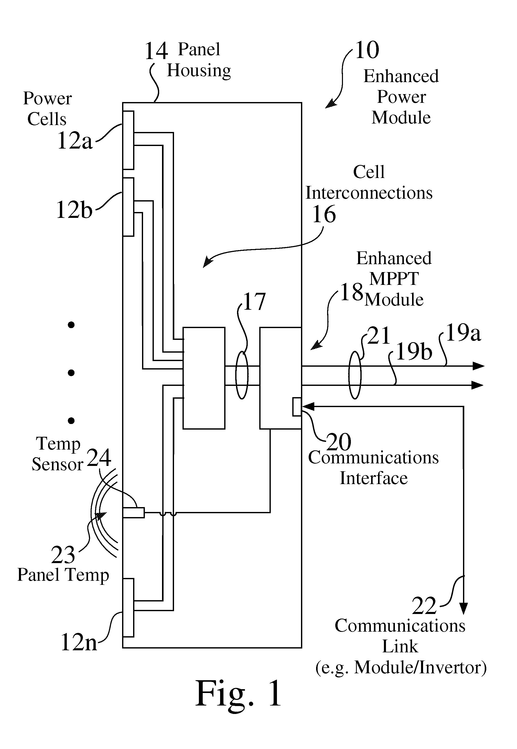
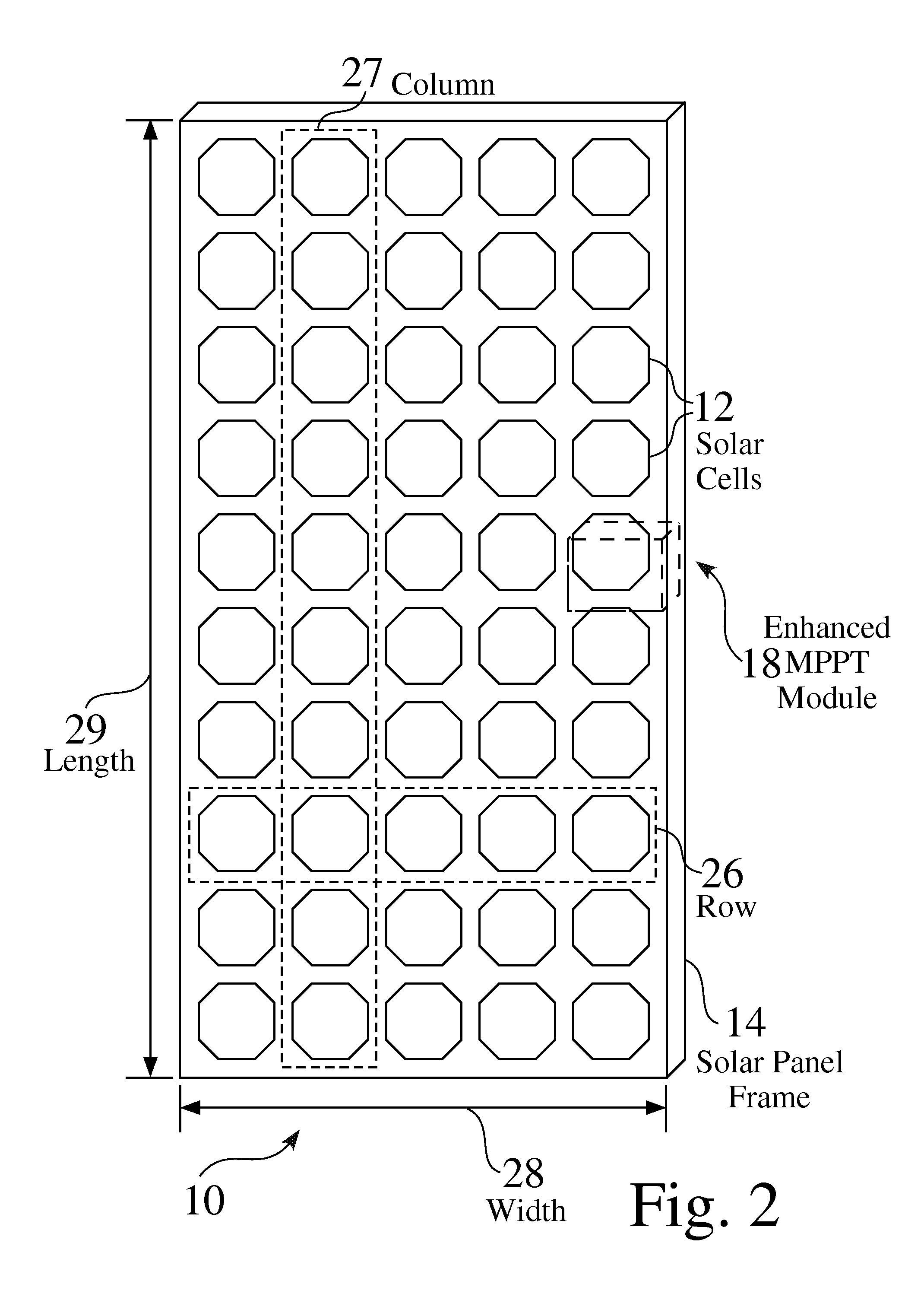
[0104]FIG. 1 is a schematic view of an exemplary enhanced power module 10 comprising a plurality of power cells 12, e.g. 12a-12n, such as but not limited to photovoltaic solar cells, fuel cells, and battery cells, connected 16,17 to a distributed maximum power point tracking (DMPPT) module 18. FIG. 2 is a schematic view of an exemplary enhanced power structure 10, e.g. an enhanced solar panel 10, comprising a plurality of solar cells 12 and a distributed maximum power point tracking module 18. FIG. 3 is a schematic view 30 of an exemplary photovoltaic solar cell having DC output power connections 17 to a DMPPT module 18. FIG. 4 is a schematic view of an exemplary solar array 34 comprising a plurality of enhanced solar panels 10, e.g. 10a-10k, arranged in a plurality of strings 36, e.g. 36a-36n.

[0105]The exemplary DMPPT module 18 seen in FIG. 1 has DC inputs 17, and a DC output 21, such as comprising a positive lead 19a and a negative lead 19b, The exemplary DMPPT module 18 also com...


PUM


Abstract

Solar power systems and structures are mountable to a power distribution structure, e.g. a power pole or tower, which supports alternating current (AC) power transmission lines. An exemplary power generation structure is fixedly attached to and extends from the power distribution structure, and comprises a mounting rack. A solar array, comprising at least one solar panel, is affixed to the mounting rack. A DC to AC invertor is connected between the DC outputs of the solar array and the AC power transmission lines. The length of the solar array is generally in alignment with the power distribution structure, and the width of the solar array is greater than half the is circumference of the power distribution structure. The mounting rack and solar array may preferably be rotatable, such as based on any of location, time of day, or available light.

Description

CROSS REFERENCE TO RELATED APPLICATIONS[0001]This Application Claims Priority to U.S. Provisional Application No. 61 / 534,802, entitled Pole-Mounted Systems, Structures and Processes with Distributed Maximum Power Point Tracking and Tracking Mechanisms, filed 14 Sep. 2011, which is incorporated herein in its entirety by this reference thereto.[0002]The Application is also a Continuation in Part and claims priority for commonly disclosed matter to PCT Application No. PCT / US2010 / 045352, entitled Enhanced Solar Panels, Liquid Delivery Systems and Associated Processes for Solar Energy Systems, filed 12 Aug. 2010, which claims priority to U.S. Provisional Application No. 61 / 234,181, entitled Distributed Maximum Power Point Tracking System, Structure, and Process with Enhanced Solar Panel Coating, Cleaning and Cooling, filed 14 Aug. 2009, which are each incorporated herein in their entirety by this reference thereto.[0003]PCT Application No. PCT / US2010 / 045352 is also a Continuation in Part...

Claims


Application Information

Patent Timeline
Patent Type & Authority Applications(United States)
IPC IPC(8): H02J3/00H01L31/042
CPCH01L31/042H02J3/385Y02E10/58H02J13/0062H02J13/0079Y02B90/2638H02S50/10Y04S40/124Y04S10/30Y02E60/74Y02E40/72H01L31/02021Y04S10/123H02J13/00002H02J2300/26H02J3/381H02J13/00016H02J13/00028Y02B90/20Y02E10/56Y02E10/76Y02E40/70Y02E60/00H02M7/44H02S20/32H02S40/32
Inventor NEWDOLL, RONALD M.SHAVER, II, ARGIL E.
Owner ACCURATE SOLAR POWER LLC
Why Eureka
Try Eureka