Power-receiving device, wireless power-feeding system including power-receiving device, and wireless communication system including power-receiving device

a technology of wireless power-feeding system and power-feeding device, which is applied in the direction of near-field systems using receivers, inductances, transformers, etc., can solve the problems of increasing the size and cost of electronic appliances, and achieve the effect of high transmission efficiency

Inactive Publication Date: 2012-09-13
SEMICON ENERGY LAB CO LTD
View PDF7 Cites 261 Cited by
  • Summary
  • Abstract
  • Description
  • Claims
  • Application Information

AI Technical Summary

Benefits of technology

[0019]One embodiment of the present invention can provide a power-receiving device that yields high transmission efficiency and can be used for two systems, wireless power feeding and wireless communication.

Problems solved by technology

Conventionally, when a portable electronic appliance is provided with two systems, a wireless power-feeding system (hereinafter also called wireless power feeding) and a wireless communication system (hereinafter also called wireless communication), each system requires two power-receiving, devices such as a coil and an antenna, leading to a problem of increased electronic appliance size and cost.

Method used


Image

  • Power-receiving device, wireless power-feeding system including power-receiving device, and wireless communication system including power-receiving device
  • Power-receiving device, wireless power-feeding system including power-receiving device, and wireless communication system including power-receiving device
  • Power-receiving device, wireless power-feeding system including power-receiving device, and wireless communication system including power-receiving device

Examples


embodiment 1

[0030]This embodiment describes a power-receiving device according to one embodiment of the present invention with reference to FIGS. 1A to 1C, FIG. 2, and FIG. 3.

[0031]FIG. 1A is a plan view showing a power-receiving device viewed from a first surface side. FIG. 1B is a plan view showing the power-receiving device viewed from a second surface side. FIG. 1C is a cross-sectional view taken along dashed line X1-Y1 in FIGS. 1A and 1B.

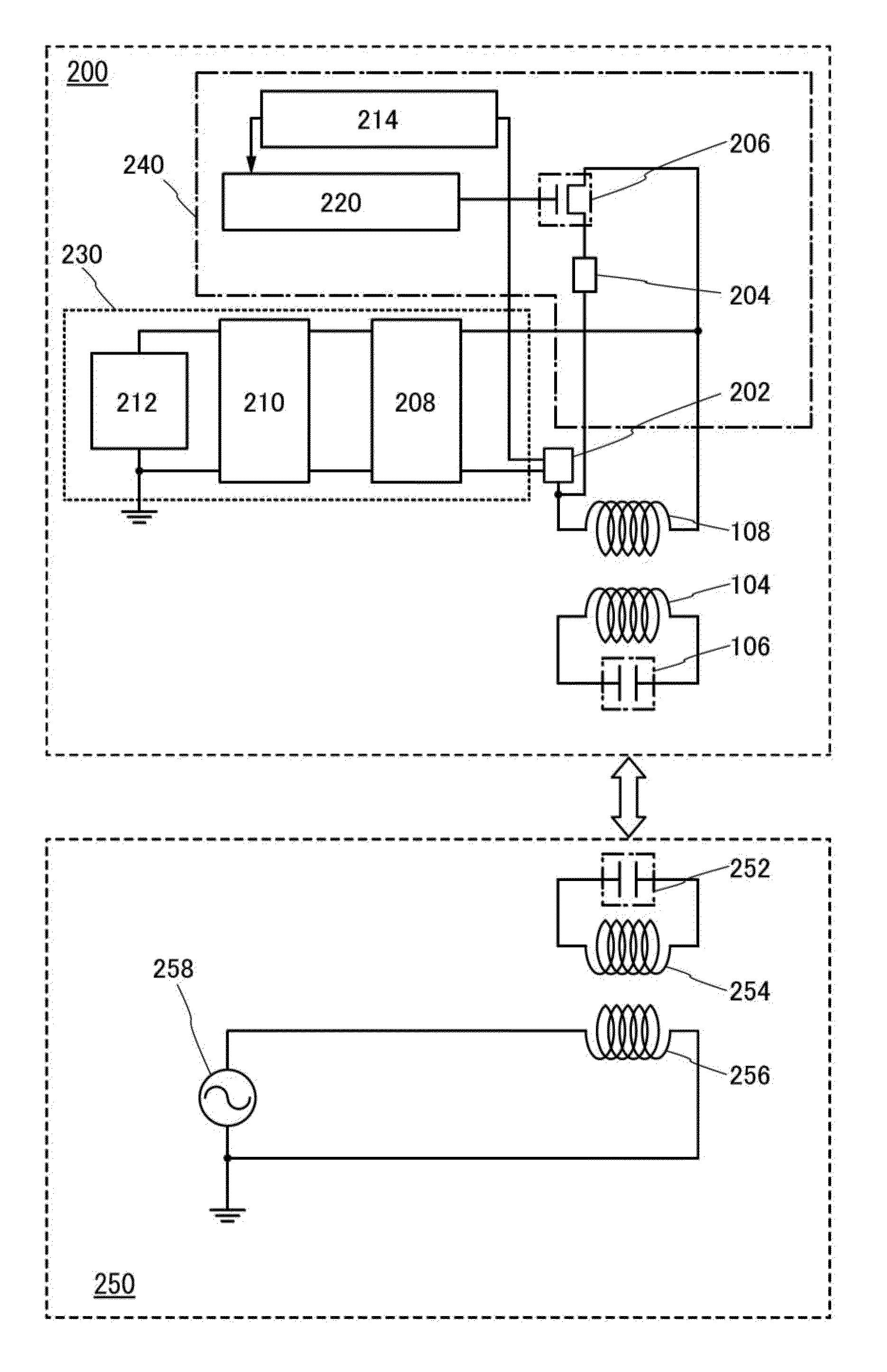
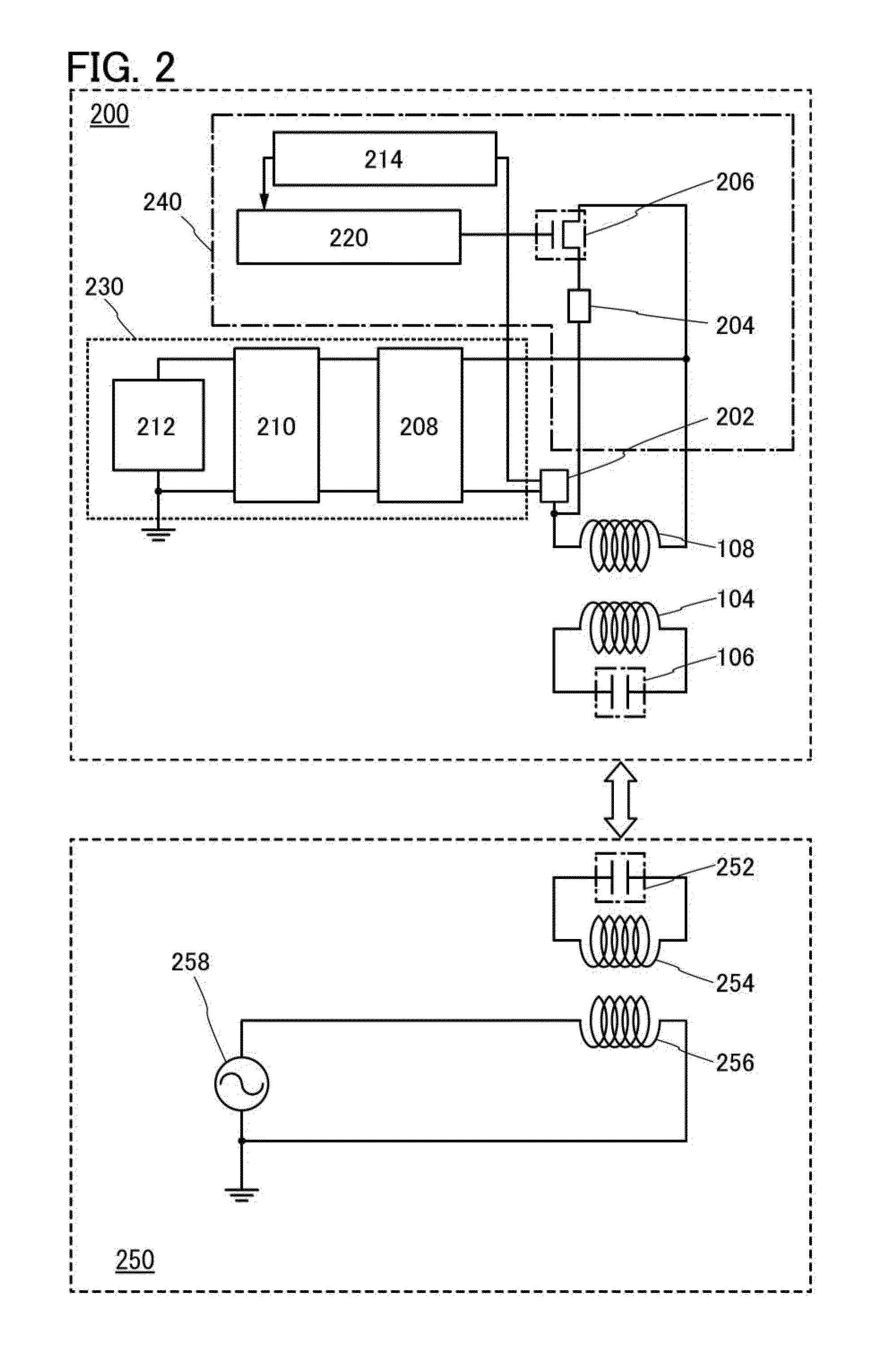
[0032]The power-receiving device shown in FIGS. 1A to 1C includes a substrate 102, a power-receiving resonance coil 104 formed over the first surface of the substrate 102, a capacitor 106 connected to the power-receiving resonance coil 104, and a power-receiving coil 108 formed over the second surface of the substrate 102.

[0033]A glass epoxy substrate, a glass composite substrate, a paper-phenolic substrate, or a flexible substrate such as a film can be used as the substrate 102.

[0034]The power-receiving resonance coil 104 formed over the first surface of ...

embodiment 2

[0071]In this embodiment, applications of a wireless power-feeding system using the power-receiving device described in the above embodiment are described. Examples of the applications of the wireless power feeding system using the power-receiving device according to one embodiment of the present invention include portable electronic devices such as a digital video camera and a personal digital assistant (e.g., a mobile computer, a cellular phone, a portable game machine, and an e-book reader). Examples will be described bellow refereeing to drawings.

[0072]FIG. 4A shows an example in which a wireless power-feeding system is used for a cellular phone and a personal digital assistant and which is composed of a power-transmitting device 700, a power plug 702, and a cellular phone 704 including a power-receiving device 706, and a cellular phone 708 including a power-receiving device 710. A wireless power-feeding system using the power-receiving device described in the above embodiment i...

example 1

[0082]In Example 1, a wireless power-feeding system with a simple structure was evaluated by using the power-receiving device in FIG. 1 described in Embodiment 1. Description will be given with reference to FIGS. 5A to 5E and FIG. 6.

[0083]FIG. 5A is a plan view of a power-receiving device 500, which shows a substrate 502 viewed from a first surface side. FIG. 5B is a plan view of the power-receiving device 500, which shows the substrate 502 viewed from a second surface side. FIG. 5C is a cross-sectional view taken along dashed line X2-Y2 in FIGS. 5A and 5B. FIG. 5D is a plan view of a power-transmitting device 550. FIG. 5E is a cross-sectional view taken along dashed line V-W in FIG. 5D.

[0084]The power-receiving device 500 includes the substrate 502, a power-receiving resonance coil 504, a capacitor 506, a power-receiving coil 508, wiring 510, a socket 512, and a bulb 514.

[0085]The substrate 502 is a glass epoxy substrate that measures 4.2 cm wide by 7.2 cm long by 0.7 mm thick. The...


PUM


Abstract

When a portable electronic appliance is provided with two systems, a wireless power-feeding system and a wireless communication system, each system requires two power-receiving devices, a coil and an antenna, leading to a problem of increased electronic appliance size and cost. Wireless power feeding employs the resonance method and uses a resonance coil using the resonance method and a power-receiving coil that receives power from the resonance coil. At least one of the resonance coil and the power-receiving coil can also be used as an antenna for wireless communication. Thus, a power-receiving device that can be used for two systems, wireless power feeding and wireless communication, can be provided.

Description

BACKGROUND OF THE INVENTION[0001]1. Field of the Invention[0002]The present invention relates to a power-receiving device, a wireless power-feeding system including the power-receiving device, and a wireless communication system including the power-receiving device.[0003]2. Description of the Related Art[0004]Various electronic appliances have spread and a variety of products is shipped to the market. In recent years, the spread of portable electronic appliances such as cellular phones and digital video cameras is apparent.[0005]A cellular phone or a digital video camera has a built-in battery serving as a power storage means. Currently, such a battery is charged, in most cases, by bringing it in direct contact with a household AC power source serving as a power-feeding means. In view of this, research and development of methods of wirelessly charging batteries or feeding electricity to loads for improved convenience have advanced. Typical examples of methods for wireless power-feed...

Claims


Application Information

Patent Timeline
Patent Type & Authority Applications(United States)
IPC IPC(8): H02J17/00H04B5/02
CPCH02J7/0027H02J17/00H04B5/0093H02J5/005H04B5/0037H02J7/0044H02J50/12H02J50/80H02J50/40H02J50/005H02J2310/22
Inventor KAMATA, KOICHIRO
Owner SEMICON ENERGY LAB CO LTD
Why Eureka
Try Eureka