

Contactor draw out tray
a contactor and tray technology, applied in the direction of coupling device connection, electrical apparatus construction details, engagement/disengagement of coupling parts, etc., can solve the problems of difficult repair and maintenance of equipment, difficult task for longwall power centers, and inability to evacuate defective equipment to the surface, so as to achieve the effect of easy repair
- Summary
- Abstract
- Description
- Claims
- Application Information
AI Technical Summary
Benefits of technology
Problems solved by technology
Method used
Image

Examples
Embodiment Construction
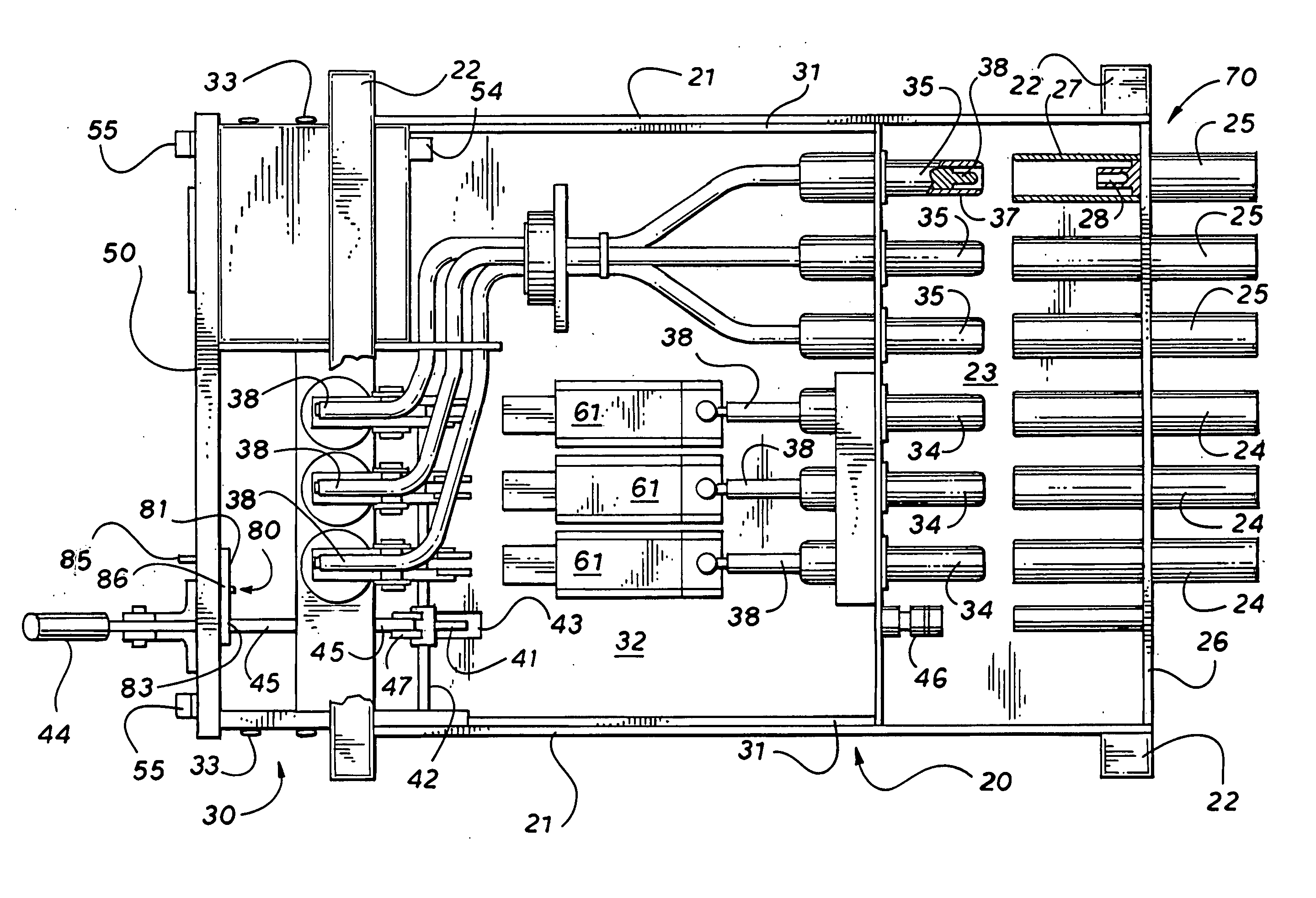
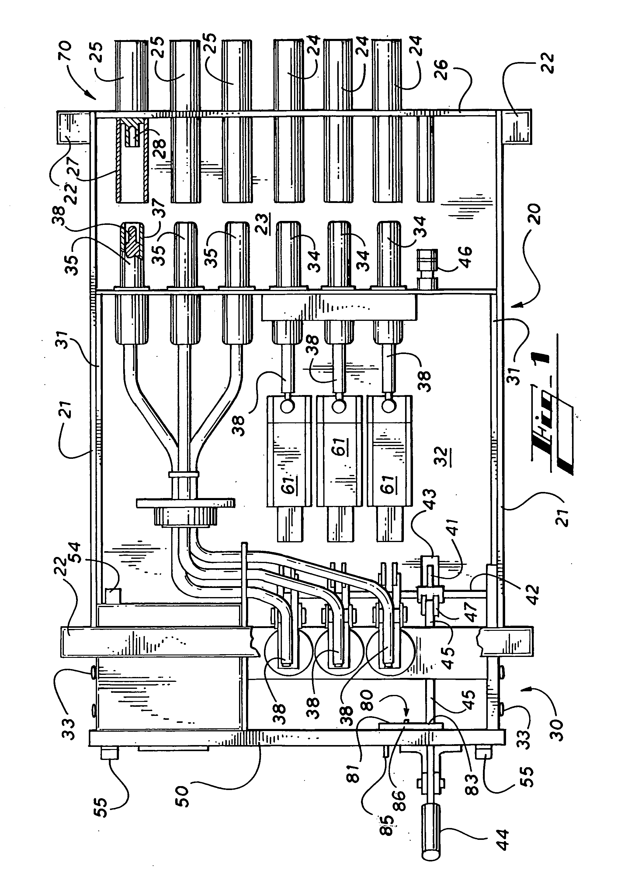
[0018] Referring to the drawings for a fuller understanding of the invention, FIG. 1 shows an exemplary embodiment of an electrical contactor tray of the present invention. The contactor tray comprises a stationary frame 20, a movable frame 30, a front panel 50, and a rear panel 70.
[0019] Stationary frame 20 generally comprises a pair of longitudinal support rails 21, end supports 22, and a base plate 23 for supporting the electrical components carried by the stationary frame 20. Preferably base plate 23 will extend between support rails 21 and end supports 22 to prevent the infiltration of dust, moisture and other contaminants from beneath the apparatus which might adversely effect the longevity and performance of the electrical components.
[0020] Stationary frame 20 may further comprise a suitable enclosure (not shown) to protect the electrical components from the aforementioned environmental hazards, such that the apparatus may be utilized in a stand alone configuration. More pr...
PUM
 Abstract
Description
Claims
Application Information