Optical pickup actuator

a technology of optical pickup actuator and actuator, which is applied in the direction of instruments, record information storage, transportation and packaging, etc., can solve the problems of correction errors and complicated drive circuits, and achieve the effects of reducing drive errors, increasing magnetic driving force, and improving arrangement structur

Inactive Publication Date: 2007-08-30
TOSHIBA SAMSUNG STORAGE TECH KOREA CORP
View PDF5 Cites 2 Cited by
  • Summary
  • Abstract
  • Description
  • Claims
  • Application Information

AI Technical Summary

Benefits of technology

[0015]Accordingly, it is an aspect of the present invention to provide an optical actuator using a fine pattern coil which increases a magnetic driving force by improving the arrangement structure between the focus coil and the magnet and reduce a drive error by configuring an independent tilt coil.

Problems solved by technology

Thus, since the conventional optical pickup actuator includes a structure to perform both focus driving and tilt driving using the first and second focus coils 12a and 12b, a drive circuit is complicated and a correction error may be generated when the driving to correct a focus error and the driving to correct a tilt error are simultaneously performed.

Method used


Image

  • Optical pickup actuator
  • Optical pickup actuator
  • Optical pickup actuator

Examples


Embodiment Construction

[0028]Reference will now be made in detail to the embodiments of the present invention, examples of which are illustrated in the accompanying drawings, wherein like reference numerals refer to the like elements throughout. The embodiments are described below to explain the present invention by referring to the figures.

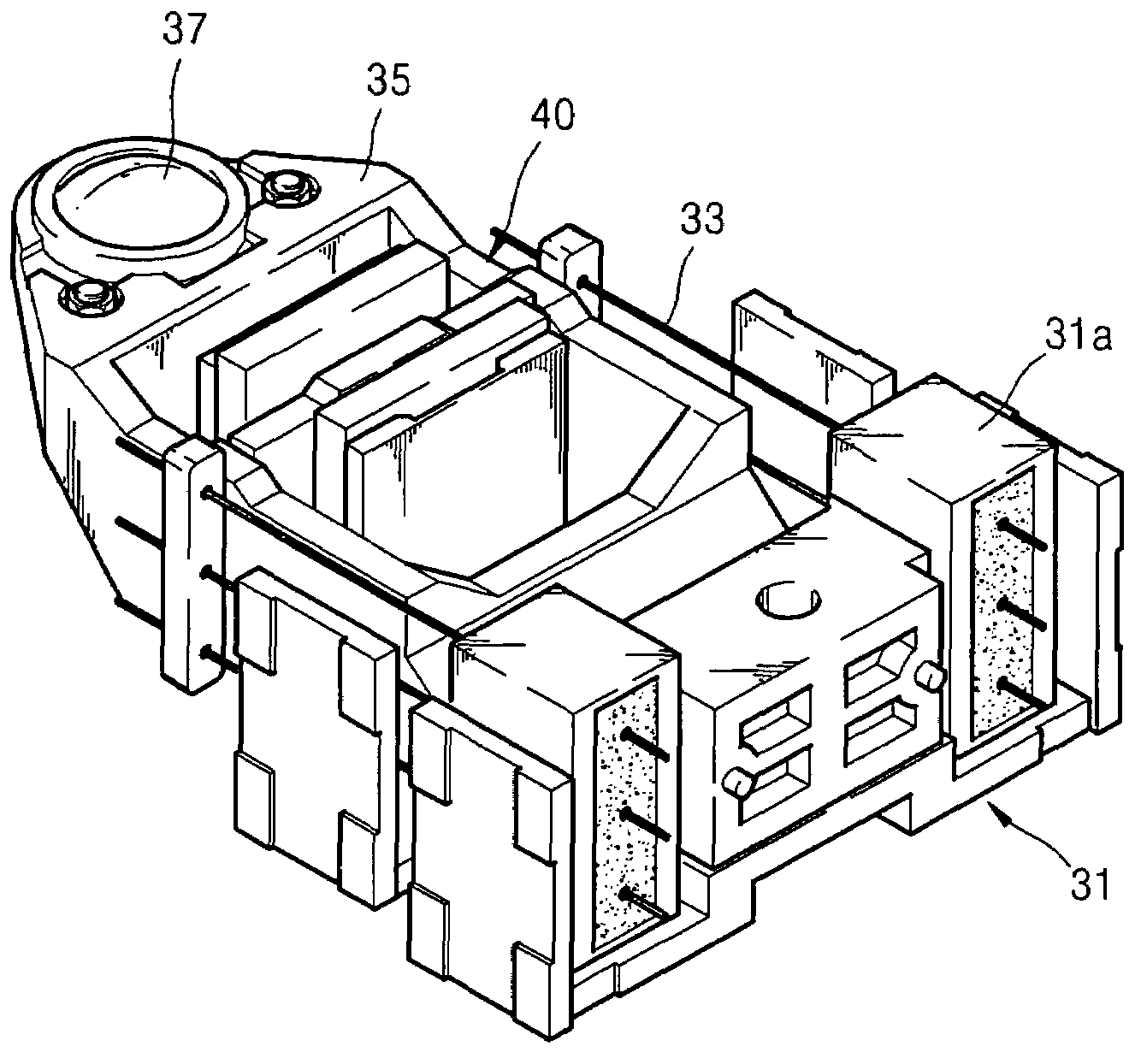
[0029]FIGS. 4 and 5 are a perspective view and a plan view of an optical pickup actuator according to an embodiment of the present invention. FIG. 6 is a cross-sectional view of a major part of the optical pickup actuator of FIG. 4. As shown in FIGS. 4-6, an optical pickup actuator according to an embodiment of the present invention comprises a base 31, a blade 35 on which an objective lens 37 is mounted, a plurality of suspensions 33 supporting the blade 35 to be movable with respect to the base 37, and a magnetic circuit 40 driving the blade 35. The suspensions 33 provide electroconductive paths through which current is applied to a fine pattern coil 41 which constit...


PUM

PropertyMeasurementUnit
currentaaaaaaaaaa
currentaaaaaaaaaa
magneticaaaaaaaaaa

Abstract

An optical pickup actuator which includes a base, a blade having an objective lens mounted thereon, a plurality of suspensions supporting the blade to be movable with respect to the base and forming an electroconductive path, and a magnetic circuit driving the blade according to a driving signal applied through the respective suspensions. The magnetic circuit includes a magnet fixed to the base, and a fine pattern coil installed on the blade at a position facing the magnet and having a track pattern coil, a focus pattern coil, and a tilt pattern coil independently driven by current applied through the suspensions and providing driving forces in a track direction, a focus direction, and a tilt direction of the blade.

Description

CROSS-REFERENCE TO RELATED APPLICATIONS[0001]This application claims the benefit of Korean Patent Application No. 10-2006-0018519, filed on Feb. 25, 2006, in the Korean Intellectual Property Office, the disclosure of which is incorporated herein in its entirety by reference.BACKGROUND OF THE INVENTION[0002]1. Field of the Invention[0003]The present invention relates to an optical pickup actuator used for an optical recording and reproducing apparatus. More particularly, to a slim-type 3-axis driving optical pickup actuator using a fine pattern coil (FPC).[0004]2. Description of the Related Art[0005]A conventional optical pickup is used for an optical recording and reproducing apparatus and performs recording and / or reproduction of information in a non-contact manner with respect to an optical disk (i.e., an information storage medium). The optical pickup requires an optical pickup actuator capable of driving an objective lens in a track direction, a focus direction, and / or a tilt di...

Claims


Application Information

Patent Timeline
Patent Type & Authority Applications(United States)
IPC IPC(8): G11B7/00
CPCG11B7/0933G11B7/0956G11B7/0935B60N3/106B60N2/242B60Y2200/143
Inventor YOON, SANG-YOLJANG, DAE-JONGLEE, YOUNG-BINLEE, YONG-JAERYOO, BYUNG-RYULLEE, YOUNG-WON
Owner TOSHIBA SAMSUNG STORAGE TECH KOREA CORP
Why Eureka
Try Eureka