
Ventilator for casting mold

a technology for ventilators and casting molds, applied in the direction of manufacturing tools, foundry patterns, foundry moulding apparatus, etc., can solve the problems of difficult to perform the role of ventilators, deterioration of gas emission efficiency, and deterioration of durability, so as to improve gas emission efficiency, improve arrangement structure, and prevent the effect of exhaust hole transformation

Active Publication Date: 2022-11-01
PARK DAE GEUN
View PDF4 Cites 0 Cited by
  • Summary
  • Abstract
  • Description
  • Claims
  • Application Information

AI Technical Summary

Benefits of technology

[0008]Accordingly, the present invention has been made to solve the above-mentioned problems occurring in the prior arts, and it is an object of the present invention to provide a ventilator for a casting mold, which has exhaust holes of an improved arrangement structure being shorter than a cylindrical body part so as to enhance gas emission efficiency and prevent transformation of the exhaust holes, and which has a buffering space part formed inside the cylindrical body part to spread and accept melt coming through the exhaust holes so as to effectively prevent a damage of a mold caused by external leakage of the melt.
[0013]According to the present invention, the ventilator for a casting mold has the exhaust holes which are improved in arrangement structure and are shorter than a cylindrical body part so as to enhance gas emission efficiency and prevent transformation of the exhaust holes, and has a buffering space part formed inside the cylindrical body part to spread and accept melt coming through the exhaust holes so as to effectively prevent a damage of a mold caused by external leakage of the melt.

Problems solved by technology

Meanwhile, because such a ventilator is manufactured through compression of powder, micropores are formed inside the ventilator, and it considerably deteriorates durability.
However, when the ventilator is fit to the mold, because a hole where gas moves is transformed or the entire form of the mold is deformed due to a long-term use, the ventilator is difficult to perform its role since the ventilator is separated or gas is not emitted smoothly due to distortion of the hole.
Therefore, after completion of machining, there may occur overlap of the holes due to irregular arrangement of the holes or leaning of the holes due to concentration on an edge, and it makes gas emission efficiency deteriorated and it makes molding time delayed since it takes long time to perfectly emit gas.

Method used


Image

  • Ventilator for casting mold
  • Ventilator for casting mold
  • Ventilator for casting mold

Examples


Embodiment Construction

[0020]Hereinafter, preferred embodiments of the present invention will be described in detail with reference to the accompanying drawings. In description of the invention, a detailed explanation of known related functions and constitutions may be omitted to avoid unnecessarily obscuring the subject matter of the present invention.

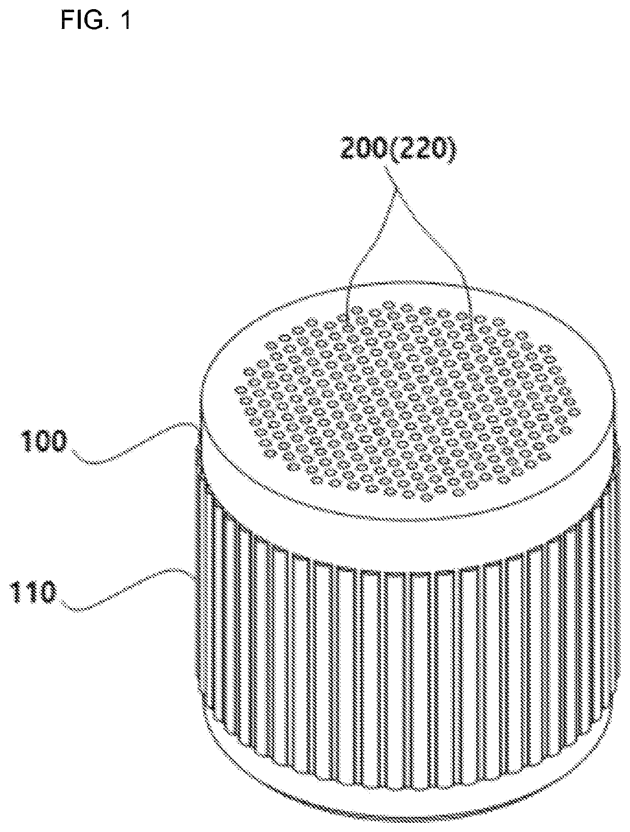
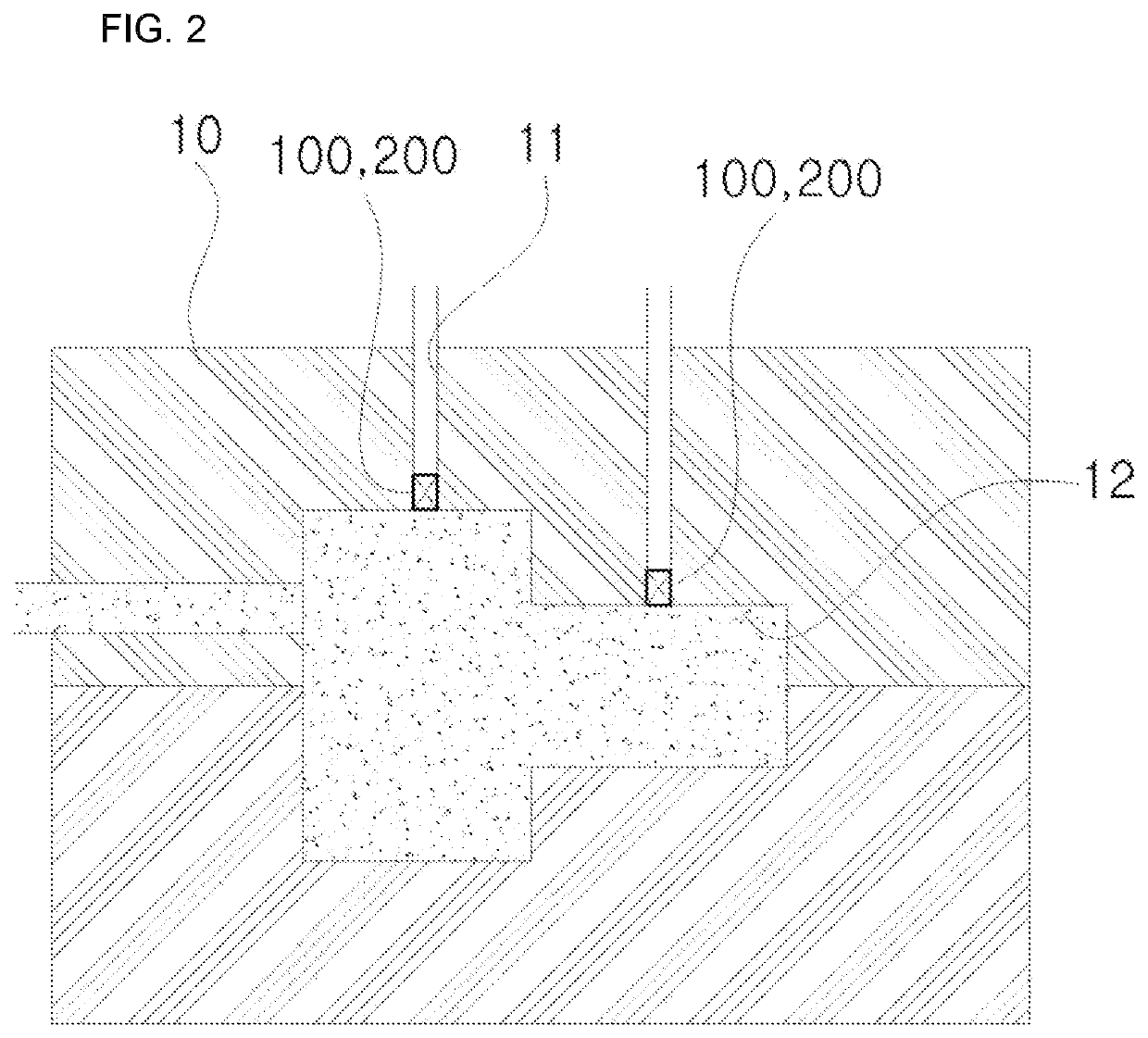
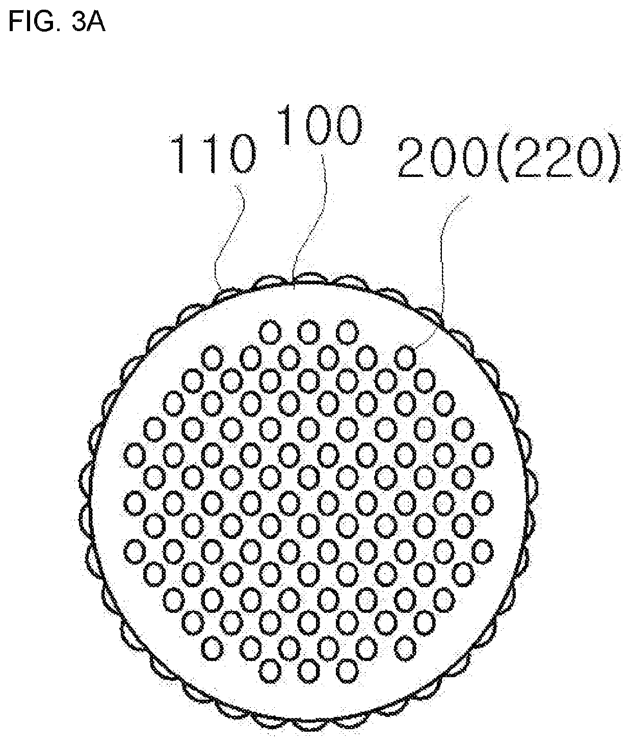
[0021]FIG. 1 is a perspective view showing a ventilator for a casting mold according to a preferred embodiment of the present invention, FIG. 2 is a view showing an installed state of the ventilator for the casting mold according to the preferred embodiment of the present invention, FIG. 3A is a plan view and FIGS. 3B and 3C are front views showing the ventilator for the casting mold according to the preferred embodiment of the present invention, FIG. 4 is a view showing an internal structure of the ventilator for the casting mold according to the preferred embodiment of the present invention, and FIGS. 5A and 5B are views showing a porous block of a ventil...


PUM

PropertyMeasurementUnit
lengthaaaaaaaaaa
areaaaaaaaaaaa
diameteraaaaaaaaaa

Abstract

A ventilator for a casting mold is mounted on an exhaust pipe (11) of a mold (10) to emit gas generated when melt is injected into a molding space (12). The ventilator for a casting mold has exhaust holes which are improved in arrangement structure and are shorter than a cylindrical body part so as to enhance gas emission efficiency and prevent transformation of the exhaust holes, and has a buffering space part formed inside a cylindrical body part to spread and accept melt coming through the exhaust holes so as to effectively prevent a damage of a mold caused by external leakage of the melt. The ventilator for the casting mold includes a cylindrical body part (100) and a fixed type exhaust block (20).

Description

BACKGROUND[0001]The present invention relates to a ventilator for a casting mold, and more particularly, to a ventilator for a casting mold, which has exhaust holes of an improved arrangement structure being shorter than a cylindrical body part so as to enhance gas emission efficiency and prevent transformation of the exhaust holes, and which has a buffering space part formed inside the cylindrical body part to spread and receive melt coming through the exhaust holes so as to effectively prevent a damage of a mold caused by external leakage of the melt.[0002]In general, a ventilator is configured to make a flow of a fluid flow only in one direction through fine holes parallel to each other, and is used to expel air or generated gas in a mold for sound casting without any defect, such as bad pouring, formation of cold shut, and others in gravity casting, low pressure casting, and plastic injection molding.[0003]Meanwhile, because such a ventilator is manufactured through compression ...

Claims


Application Information

Patent Timeline
Patent Type & Authority Patents(United States)
IPC IPC(8): B22C9/06
CPCB22C9/067B22C9/00B22D18/04
Inventor PARK, DAE GEUN
Owner PARK DAE GEUN
Learn More