System and Method For Shade Selection Using a Fabric Brightness Factor

a fabric brightness factor and fabric technology, applied in the direction of optical radiation measurement, instruments, knitting, etc., can solve the problems of creating both problems and opportunities, hvac systems not being sufficiently adjusted, shgf not addressing the comfort factor of direct solar radiation, visual, etc., to facilitate daylighting optimization, reduce artificial electric lighting needs, and minimize glare conditions

Active Publication Date: 2007-12-20
MECHOSHADE SYST LLC
View PDF2 Cites 27 Cited by
  • Summary
  • Abstract
  • Description
  • Claims
  • Application Information

AI Technical Summary

Benefits of technology

[0014]The present invention includes a system and method for determining a brightness factor associated with an illuminated window shade fabric to help determine the optimum window shade fabric for a particular room, building or other enclosure. The brightness factor incorporates the openness factor of the fabric, visible light reflectance of the fabric and visible light transmission of the fabric. The brightness factor information of the present invention may be used by architects, designers, engineers and the like to select the optimum fabric based on desired interior function, light level, the relative surface brightness, and / or any other desired interior lighting characteristic. The fabric selection may effect the building envelope by, for example, facilitating the optimization of daylighting, reduction of artificial electric lighting needs, and minimization of glare conditions.

Problems solved by technology

Such increasing use of higher visual light transmission glass creates both problems and opportunities.
However, the HVAC systems have not been sufficiently adjusted for the substantial gain in VLt which also has a strong direct solar radiant component.
However, the SHGF does not address the comfort factors of direct solar radiation, or visual brightness near the window wall (i.e., 15-20 feet from the window wall).

Method used


Image

  • System and Method For Shade Selection Using a Fabric Brightness Factor
  • System and Method For Shade Selection Using a Fabric Brightness Factor
  • System and Method For Shade Selection Using a Fabric Brightness Factor

Examples


Embodiment Construction

[0021]The detailed description of exemplary embodiments of the invention herein shows the exemplary embodiment by way of illustration and its best mode. While these exemplary embodiments are described in sufficient detail to enable those skilled in the art to practice the invention, it should be understood that other embodiments may be realized and that logical and mechanical changes may be made without departing from the spirit and scope of the invention. Thus, the detailed description herein is presented for purposes of illustration only and not of limitation. For example, the steps recited in any of the method or process descriptions may be executed in any order and are not limited to the order presented.

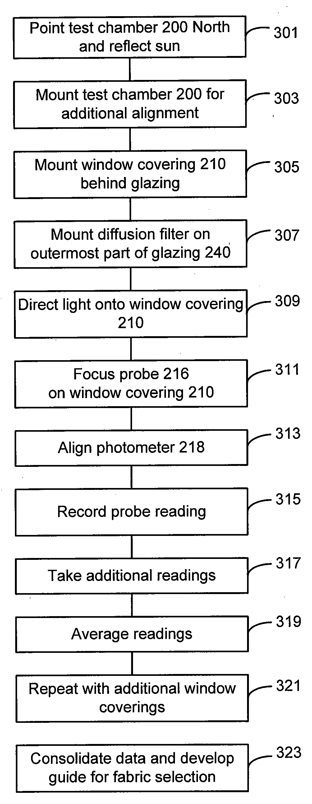
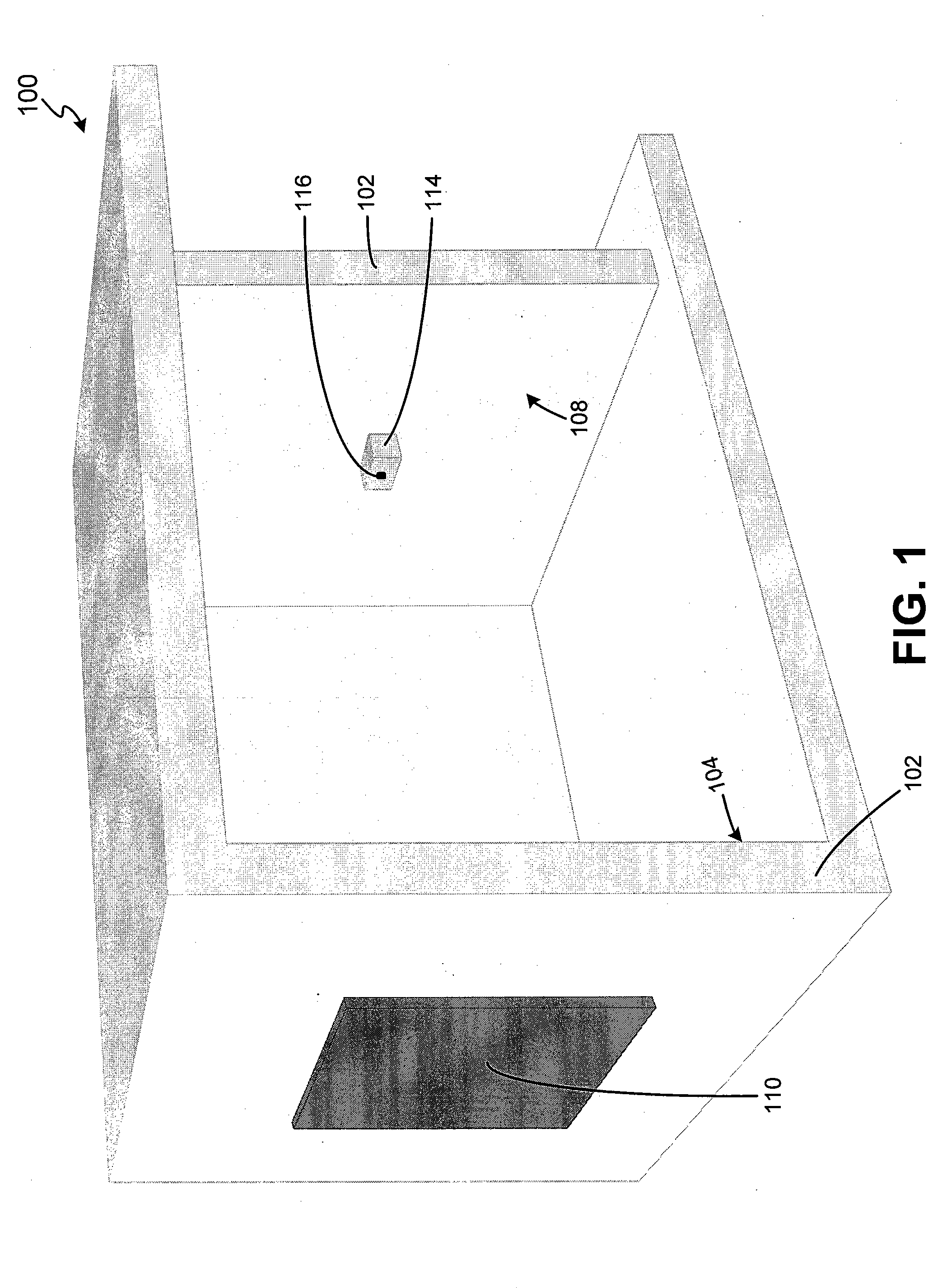
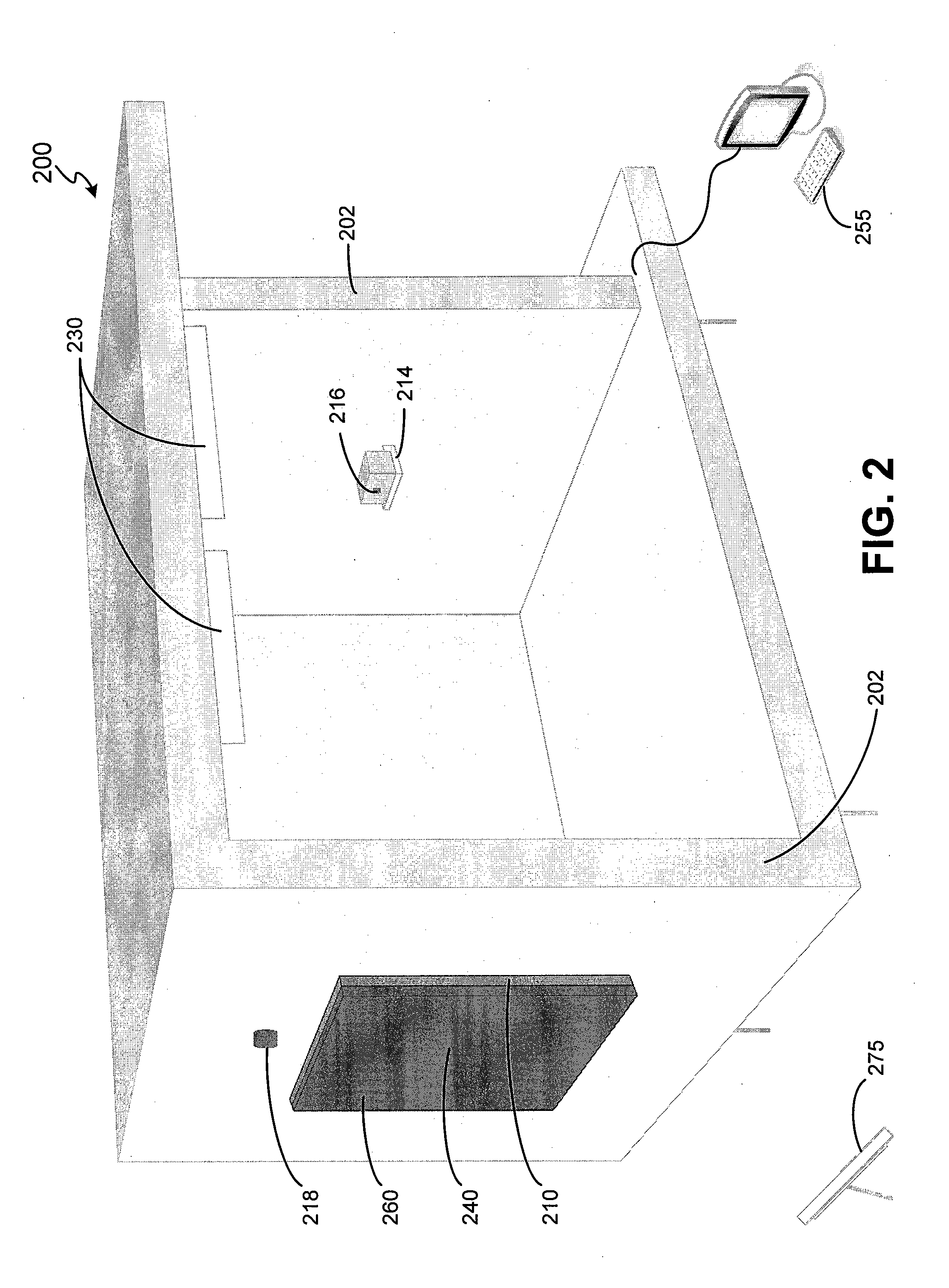
[0022]The present invention generally includes a system and method for determining the brightness factor of a fabric to help lighting designers, interior architects or other professionals to select the optimum fabric for a particular window, room, building or other location. The ...


PUM

PropertyMeasurementUnit
brightness factoraaaaaaaaaa
visible light reflectanceaaaaaaaaaa
visible light transmissionaaaaaaaaaa

Abstract

A system and method for determining a brightness factor associated with a window shade fabric is disclosed. The brightness factor incorporates the openness factor of the fabric, visible light reflectance of the fabric and visible light transmission of the fabric. The brightness factor helps to determine the optimum window shade fabric for a particular room, building or other location. The brightness factor information may be used to select the correct fabric based on desired interior function, light level, the relative surface brightness, and / or any other desired interior characteristic. The fabric selection may affect the building envelope by, for example, facilitating the optimization of daylighting, reduction of artificial electric lighting needs, and minimization of glare conditions.

Description

CROSS REFERENCE TO RELATED APPLICATIONS[0001]This application claims priority to, and the benefit of, U.S. Provisional Application Ser. No. 60 / 804,694, filed Jun. 14, 2006 and entitled “System and Method For Shade Selection Using a Fabric Brightness Factor”, which is hereby incorporated by reference in its entirety.FIELD OF THE INVENTION[0002]The invention generally relates to the optimum selection of a window shade, and more particularly, to the use of a brightness factor for selecting the optimum window shade.BACKGROUND OF THE INVENTION[0003]Incorporating the appropriate window shades over certain windows can make a substantial difference in the aesthetics, comfort and energy savings in a room. In that regard, window shades are often utilized for a variety of purposes such as, for example, maximizing a view, maximizing daylight, blacking out a room, minimizing brightness, adjusting to climatic variables and sky conditions, minimizing heat at certain times of the year, maximizing h...

Claims


Application Information

Patent Timeline
Patent Type & Authority Applications(United States)
IPC IPC(8): G01N21/84
CPCE06B9/32G01N21/59G01N21/55Y10T442/20Y10T442/3976Y10T442/45
Inventor BERMAN, JOELBERMAN, JAN
Owner MECHOSHADE SYST LLC
Why Eureka
Try Eureka