Efficient Encoding and Decoding Methods for Representing Schedules and Processing Forward Error Correction Codes

a forward error correction and encoding technology, applied in the field of encoding and decoding data in communications systems, can solve problems such as loss of data, data transmission becomes more difficult, transmitter and/or receiver limited capacity, etc., to improve the encoding and decoding efficiency of codes, reduce computational complexity, and reduce computational complexity

Inactive Publication Date: 2008-01-31
QUALCOMM INC
View PDF26 Cites 70 Cited by
  • Summary
  • Abstract
  • Description
  • Claims
  • Application Information

AI Technical Summary

Benefits of technology

[0032] In a further aspect of the above embodiment, the data block to be processed may be segmented into sufficiently small segments such that within the fast storage resource both the original segment and the processed segment may be stored concurrently. This approach admits the use of certain optimizations which further reduce computational complexity as will be further described below.
[0033] In another embodiment, there are provided methods to improve the encoding and decoding efficiency of codes which admit decoding using the method of inactivations as described

Problems solved by technology

Lost data (erasures) are often easier to deal with than corrupted data (errors) because the recipient cannot always recognize when the transmitted data has been corrupted.
Data transmission becomes more difficult when the channel is in an adverse environment, or the transmitter and/or receiver has limited capability.
In certain applications, uninterrupted error-free communication is required over long periods of time.
In these cases the problem of data transmission is difficult even in conditions of relatively low levels of errors.
Another scenario in which data communication is difficult is where a single transmission is directed to multiple receivers that may experience widely different conditions in terms of data loss.
Often, however, a reverse channel is not available or feasible, or is available only with limited capacity.
For example, in cases in which the tr

Method used


Image

  • Efficient Encoding and Decoding Methods for Representing Schedules and Processing Forward Error Correction Codes
  • Efficient Encoding and Decoding Methods for Representing Schedules and Processing Forward Error Correction Codes
  • Efficient Encoding and Decoding Methods for Representing Schedules and Processing Forward Error Correction Codes

Examples


example hardware

Elements

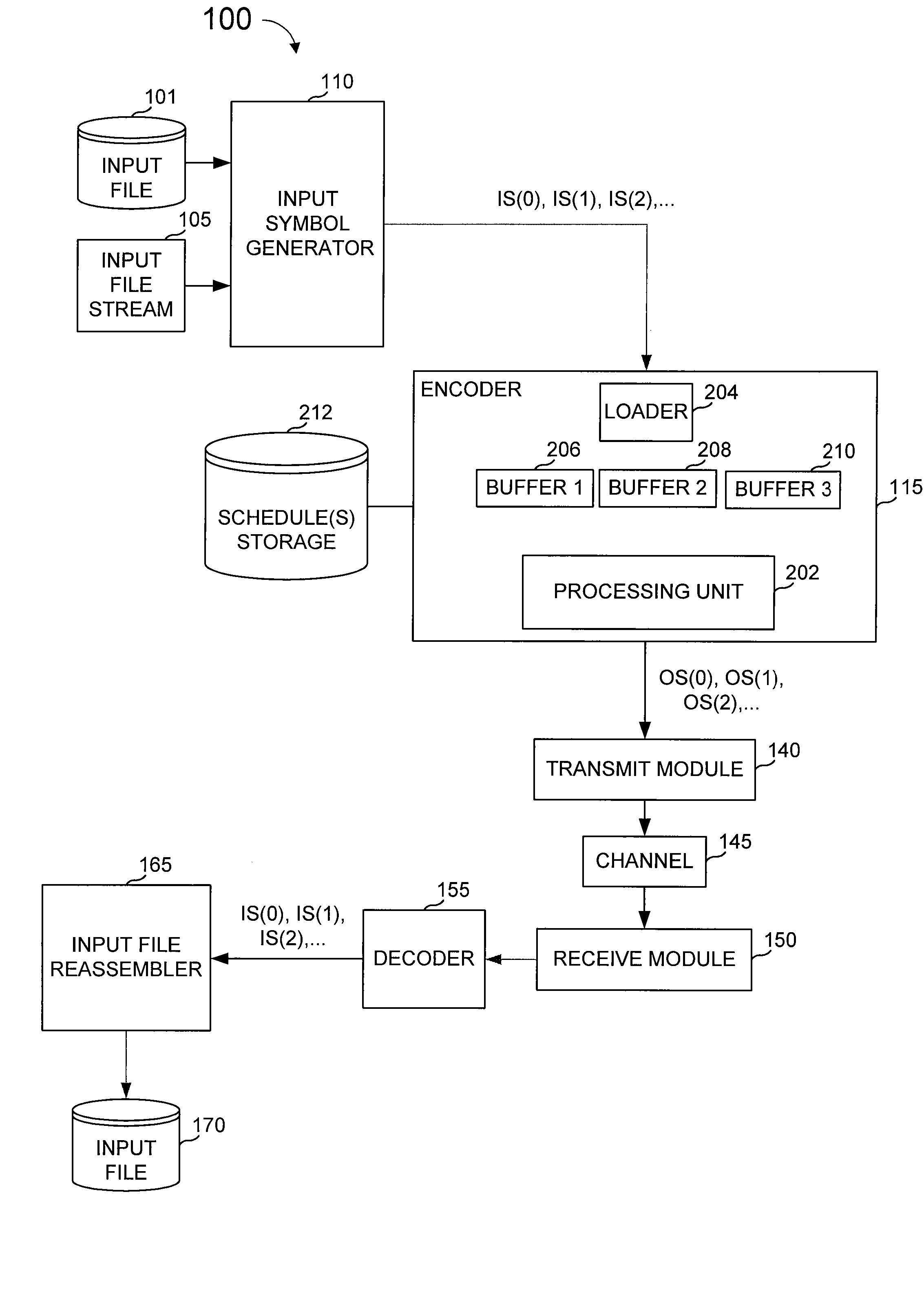
[0129]FIG. 6 is a block diagram of a communications system 100 that can be used with the present invention. In communications system 100, an input file 101, or an input stream 105, is provided to an input symbol generator 110. Input symbol generator 110 generates a sequence of one or more input symbols (IS(0), IS(1), IS(2), . . . ) from the input file or stream, with each input symbol having a value and a position (denoted in FIG. 6 as a parenthesized integer). The possible values for input symbols (source symbols), i.e., its alphabet, is typically an alphabet of 2M symbols, so that each input symbol codes for M bits of the input file. The value of M is generally determined by the use of communication system 100, but a general purpose system might include a symbol size input for input symbol generator 110 so that M can be varied from use to use.

[0130] The output of input symbol generator 110 is provided to an encoder 115. Encoder 115 might encode input symbols according to ...


PUM


Abstract

A sequence of symbol operations (a “schedule representation”) within a data storage device, wherein the operations are those used to process encoding or decoding operations of a forward error correction code (an “FEC code”) upon an arbitrary block of data of a given size (where size can be measured in numbers of symbols). The method is such that the schedule representation can be used to direct the processing of these operations upon a block of data in a way that is computationally efficient. Preferably, the same method can be applied to represent schedules derived from multiple different algorithms for the encoding or decoding of a code or for multiple different codes.

Description

CROSS-REFERENCES [0001] This application claims priority from and is a non-provisional of U.S. Provisional Patent Application No. 60 / 806,255 filed Jun. 29, 2006. [0002] The following references are included here and are incorporated by reference for all purposes: [0003] U.S. Pat. No. 6,307,487 entitled “Information Additive Code Generator and Decoder for Communication Systems” issued to Luby (hereinafter “Luby I”); [0004] U.S. Published Patent Application No. 2005 / 0257106 published Nov. 17, 2005 and entitled “File Download and Streaming System” to Luby, et al., (hereinafter “Luby II”); [0005] U.S. Pat. No. 7,068,729 entitled “Multi-Stage Code Generator and Decoder for Communication Systems” issued to Shokrollahi, et al., (hereinafter “Shokrollahi I”); [0006] U.S. Published Patent Application No. 2006 / 0036930 published Feb. 16, 2006 and entitled “Method and Apparatus for Fast Encoding of Data Symbols According to Half-Weight Codes” to Luby, et al., (hereinafter “Luby III”); [0007] U....

Claims


Application Information

Patent Timeline
IPC IPC(8): G06F11/08
CPCH03M13/3761G06F11/1008
Inventor CHEN, STEVEWATSON, MARKLUBY, MICHAEL G.SEED, BILLKUNZ, THOMAS
Owner QUALCOMM INC
Why Eureka
Try Eureka