

Endotracheal Tube Having Improved Suction Lumen
- Summary
- Abstract
- Description
- Claims
- Application Information
AI Technical Summary
Benefits of technology
Problems solved by technology
Method used
Image

Examples
Embodiment Construction
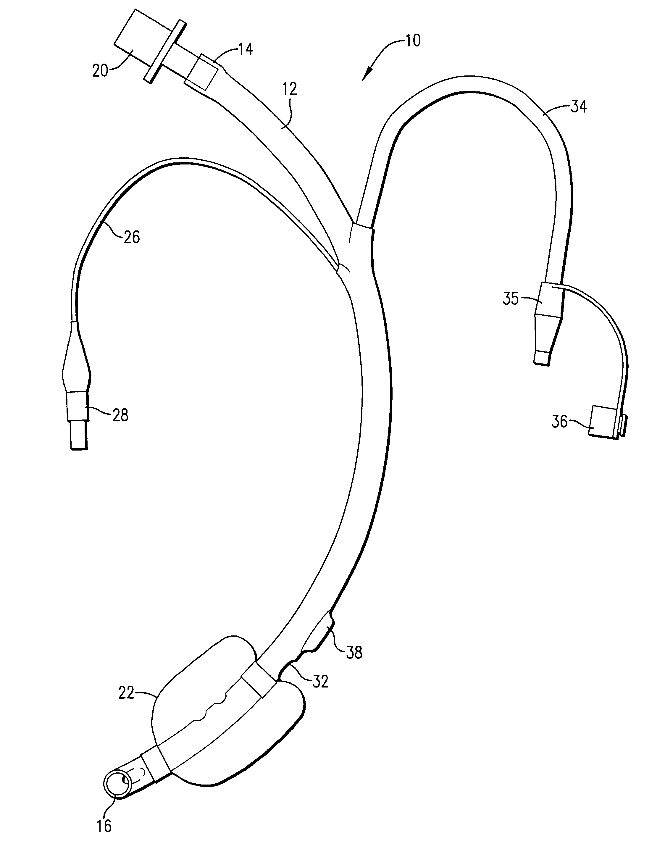
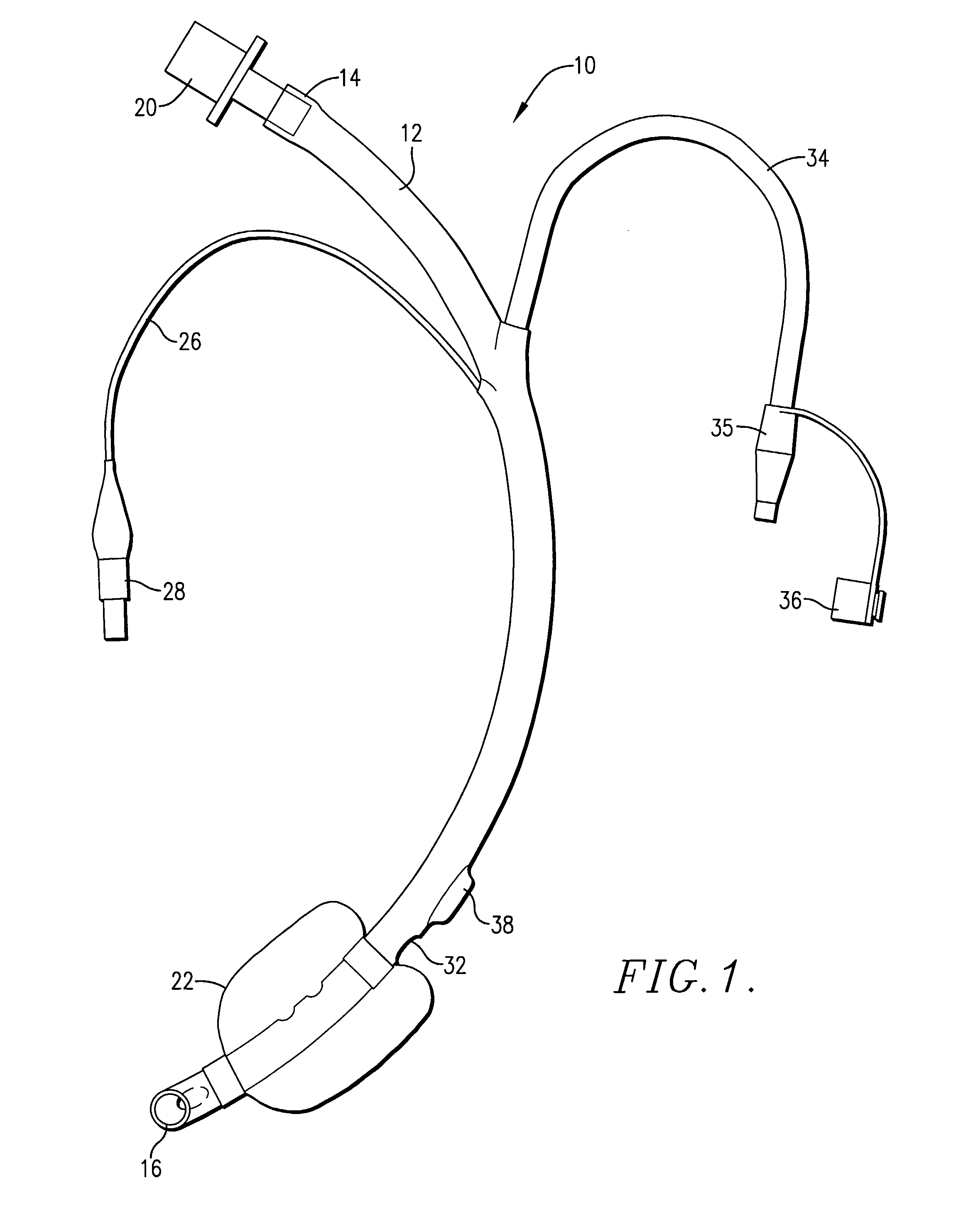
[0023] Turning now to the drawing, an exemplary endotracheal tube 10 is depicted in FIG. 1. The tube 10 includes a primary tubular body 12 having opposed, open proximal and distal ends 14 and 16. The body 12 defines a central gas-conveying passageway 18 for mechanical ventilation of a patient. The proximal end 14 is equipped with a connector 20 and, in use, the connector 20 is designed for attachment to a mechanical ventilator (not shown).
[0024] The overall tubular body 12 further includes an inflatable resilient cuff 22 adjacent the distal end thereof. During intubation of the tube 10, the cuff 22 is collapsed. However, once properly in place, the cuff 22 is fully inflated via lumen 24 formed in body 12 and having a connected proximal inflation line 26 terminating in a fixture 28 allowing such cuff inflation.
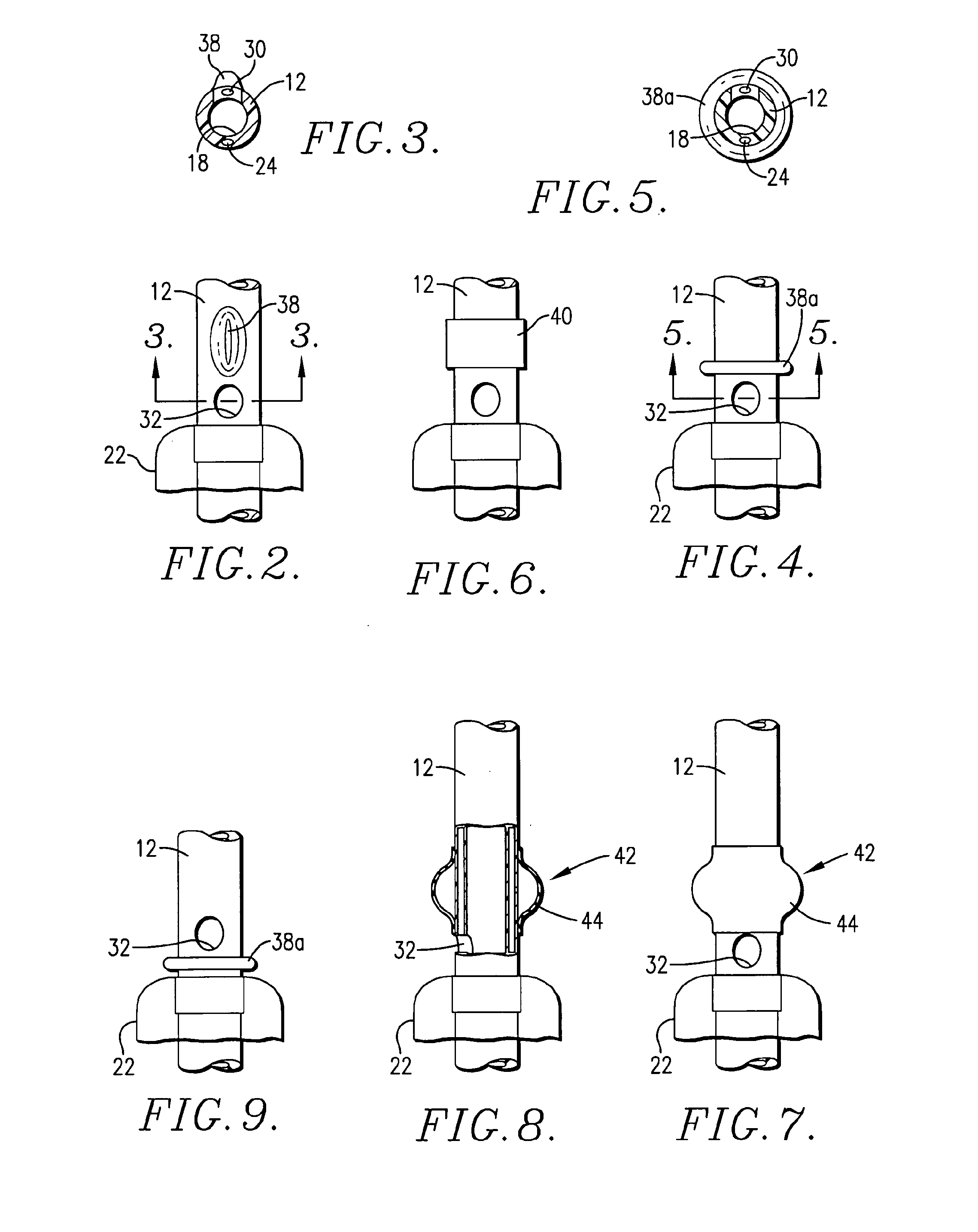
[0025] The tubular body 12 also includes a fluid removal lumen 30 situated in opposed relation to lumen 24 and likewise formed in the wall of the body 12. The lumen 30 termin...
PUM
 Abstract
Description
Claims
Application Information