Wireless communication device

a wireless communication and wireless technology, applied in the direction of resonant antennas, substantially flat resonant elements, antenna earthings, etc., can solve problems such as electrical loss, and achieve the effect of improving antenna characteristics and reducing surface waves irradiation

Inactive Publication Date: 2008-03-20
SHARP KK
View PDF11 Cites 27 Cited by
  • Summary
  • Abstract
  • Description
  • Claims
  • Application Information

AI Technical Summary

Benefits of technology

[0013]The present invention was made in view of the foregoing problems. An object of the present invention is to provide a wireless communication device capable of reducing surface waves irradiated from ends of an integrated antenna module substrate, thereby improving antenna characteristics.

Problems solved by technology

However, in a case of a wireless transmission device using millimetric waves, separately providing a high frequency circuit and an antenna and connecting them cause such a problem that electricity is lost greatly at a point where the high frequency circuit and the antenna are connected with each other.

Method used


Image

  • Wireless communication device
  • Wireless communication device
  • Wireless communication device

Examples


embodiment 1

[0030]With reference to drawings, the following explains an embodiment of the present invention.

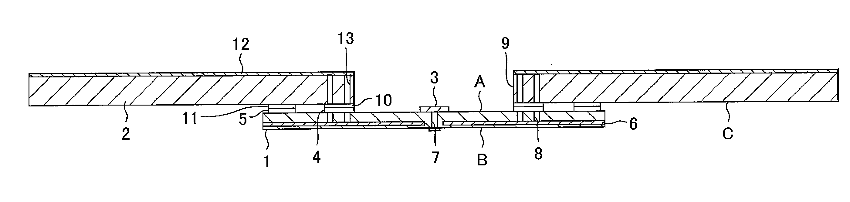
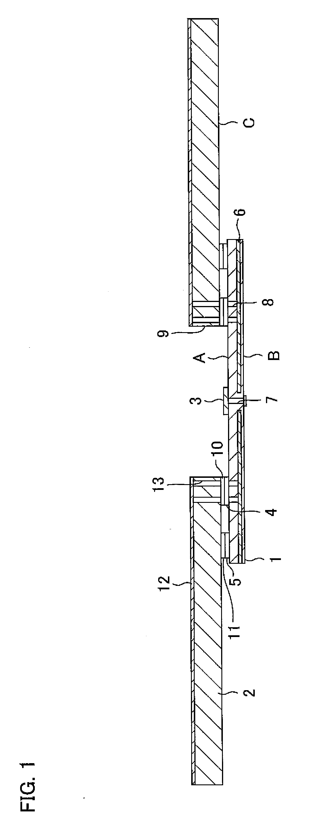
[0031]FIG. 1 is a cross sectional drawing illustrating an example of a structure of a wireless communication device of the present embodiment.

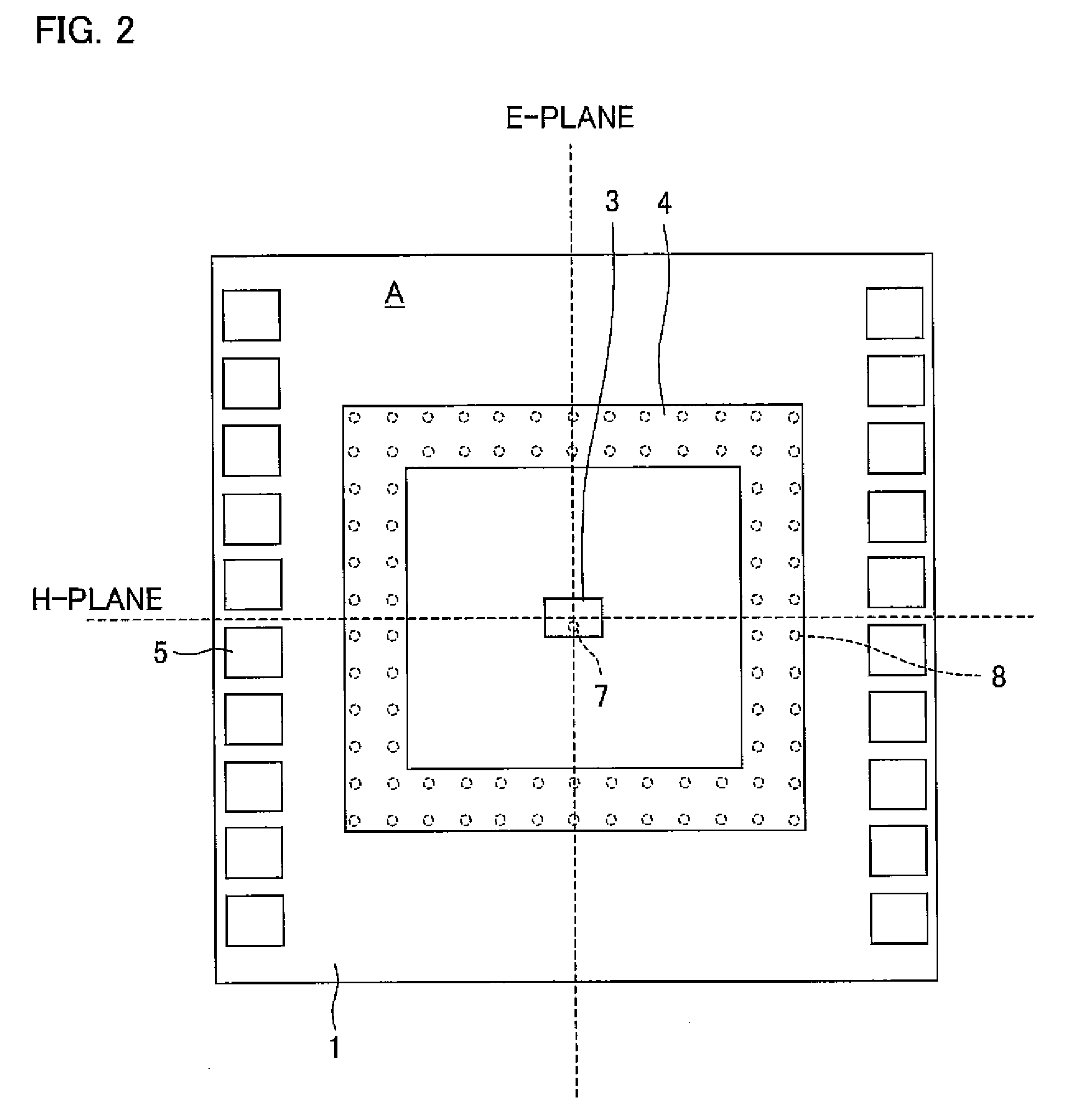
[0032]FIG. 2 is a drawing illustrating a structure of only an integrated antenna module substrate 1 of the wireless communication device in FIG. 1, when seen from a direction perpendicular to an antenna surface A where a patch antenna 3 is mounted.

[0033]Note that, detailed explanations of generation of high frequency signals and a circuit for generating high frequency signals are omitted in the present invention because an object of the present invention is improvement in antenna characteristics. Further, other parts (not shown) of the wireless communication device can be realized with conventional techniques.

[0034]An example of the wireless communication device of the present embodiment is a device for wirelessly transmitting Hi-Vision image signal...

embodiment 2

[0090]With reference to drawings, the following explains another embodiment of the present invention. Structures other than structures that will be explained in the present embodiment are the same as those in Embodiment 1. For convenience of explanation, members having the same functions as those of members illustrated in the drawings of Embodiment 1 are given the same reference signs and explanations thereof will be omitted here.

[0091]FIG. 4 is a cross sectional drawing illustrating an example of a structure of a wireless communication device of the present embodiment.

[0092]FIG. 5 is a drawing illustrating a structure of only an integrated antenna module substrate 201 of the wireless communication device in FIG. 4, the integrated antenna module substrate 201 being seen from a direction perpendicular to an antenna surface A where a patch antenna 3 is mounted.

[0093]The wireless communication device of the present embodiment includes an integrated antenna module substrate 201 and a mo...

embodiment 3

[0107]With reference to drawings, the following explains further another embodiment of the present invention. Structures other than structures that will be explained in the present embodiment are the same as those in Embodiments 1 and 2. For convenience of explanation, members having the same functions as those of members illustrated in the drawings of Embodiments 1 and 2 are given the same reference signs and explanations thereof will be omitted here.

[0108]FIG. 7 is a cross sectional drawing illustrating an example of a structure of a wireless communication device of the present embodiment.

[0109]The wireless communication device of the present embodiment is obtained by adding, to the wireless communication device of Embodiment 1, a dielectric lens 320 attached to a housing 321.

[0110]The dielectric lens 320 is made of high-density polyethylene. The dielectric lens 320 is provided so that the focus of the dielectric lens 320 corresponds to the center of the surface of the patch anten...


PUM


Abstract

A wireless communication device includes: a high frequency circuit for generating a high frequency signal, the high frequency circuit being provided on a high-frequency-circuit surface of an integrated antenna module substrate mounted on a mounting substrate; a patch antenna for irradiating radio waves indicative of the generated high frequency signal, the patch antenna being provided on an antenna surface of the integrated antenna module substrate; and a ring-shaped grounding surface provided on the antenna surface of the integrated antenna module substrate so as to surround the patch antenna. This allows reducing surface waves irradiated from the end of the integrated antenna module substrate and improving antenna characteristics.

Description

[0001]This non-provisional application claims priority under 35 U.S.C. § 119(a) on Patent Application No. 251754 / 2006 filed in Japan on Sep. 15, 2006, the entire contents of which are hereby incorporated by reference.FIELD OF THE INVENTION[0002]The present invention relates to a wireless communication device. In particular, the present invention relates to a microwave / millimetric wave wireless communication device having an antenna function.BACKGROUND OF THE INVENTION[0003]Recently, as communications systems have developed, much notice is paid to wireless transmission of Hi-Vision image signals. High-Vision image signals must transmit large amount of information and accordingly wireless transmission devices using millimetric waves that assure wide band have been developed.[0004]A wireless transmission device includes, for example, a high frequency circuit for converting a transmission signal into a high frequency signal; and an antenna for transmitting the high frequency signal as r...

Claims


Application Information

Patent Timeline
Patent Type & Authority Applications(United States)
IPC IPC(8): H01Q9/04H01Q1/38
CPCH01Q9/0407H01Q1/38
Inventor YAMADA, ATSUSHI
Owner SHARP KK
Why Eureka
Try Eureka