Microwave antenna apparatus
a technology of antenna apparatus and microwave, applied in the direction of cross-talk/noise/interference reduction, instruments, and semiconductor/solid-state device details, etc., can solve the problems of distorted radiation pattern, high amount of parasitic radiation to all directions, and narrow bandwidth (1-5%)
- Summary
- Abstract
- Description
- Claims
- Application Information
AI Technical Summary
Benefits of technology
Problems solved by technology
Method used
Image
Examples
first embodiment
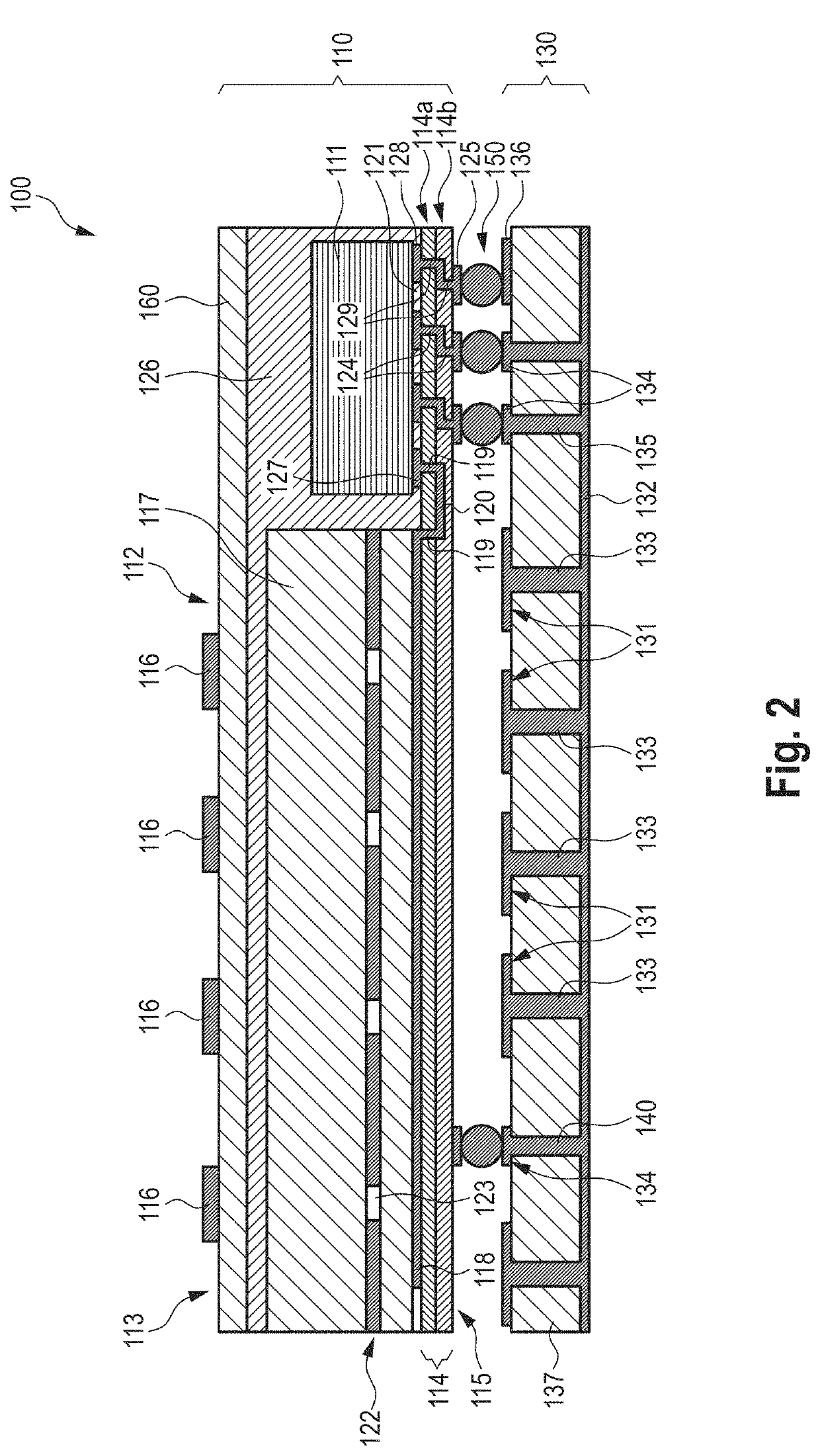
[0035]The present disclosure presents a solution for this problem by adding an electromagnetic band gap (EBG) structure below the package module as illustrated in FIG. 2 showing a microwave antenna apparatus 100 according to the present disclosure. The microwave antenna apparatus 100 generally comprises a package module 110 and an EBG module 130 coupled to the package module 110, in particular to a redistribution layer of the package module 110, via solder balls 150.
[0036]The package module 110 generally comprises a semiconductor unit 111 (also called chip), an antenna unit 112 arranged on a first side 113 of the package module 110 and a redistribution layer (RDL) unit 114 (in this embodiment comprising two redistribution layers 114a, 114b; in other embodiments comprising a redistribution layer) arranged on a second side 115 of the package module 110 opposite the first side 113. The semiconductor unit 111 is embedded in a mold layer 126. The antenna elements 116 are provided on top ...
second embodiment
[0046]FIG. 7 shows a microwave antenna apparatus 400 according to the present disclosure. As far as possible the same reference numeral are used as in FIG. 2 to reference the same elements.
[0047]The microwave antenna apparatus 400 comprises a semiconductor package module 410, an EBG module 430 coupled to the semiconductor package module 410 via solder balls 150 and a PoP antenna module 450 coupled to the semiconductor package module 410 via solder balls 151. A first RDL layer group 114a (comprising one or more polymer layer or RDL layers) is arranged on the bottom side of the semiconductor package module 410 and a second RDL layer group 114b is arranged on the top side of the semiconductor package module 410. Thus, in this embodiment separate RDL layer groups 114a, 114b are arranged on two sides of the semiconductor package module 410.
[0048]In this embodiment the RF signal is coupled from the chip 111 to the antenna elements 116 via the microstrip through the coupling element 117 as...
embodiment 3
[0082]4. Microwave antenna apparatus as defined in embodiment 3,
[0083]wherein the EBG area has at least the same size as the antenna area.
[0084]5. Microwave antenna apparatus as defined in embodiment 3 or 3,
[0085]wherein the EBG module comprises a ground layer arranged on the first surface of the EBG module around the EBG area.
[0086]6. Microwave antenna apparatus as defined in any one of embodiments 2 to 5,
[0087]wherein the one or more EBG cells are mushroom type EBG cells, uni-planar type EBG cells, polarization dependent EBG cells, compact spiral EBG cells, stacked EBG cells, miniaturized EBG cells, or interdigital capacitor EBG cells.
[0088]7. Microwave antenna apparatus as defined in any preceding embodiment,
[0089]wherein the EBG module comprises an EBG substrate layer, one or more EBG patches arranged on a first surface of the EBG substrate layer facing the package module, and one or more solder ball pads arranged on the first surface of the EBG substrate layer and contacting th...
PUM
 Abstract
Description
Claims
Application Information
 - R&D
- Intellectual Property
- Life Sciences
- Materials
- Tech Scout
- Unparalleled Data Quality
- Higher Quality Content
- 60% Fewer Hallucinations
Browse by: Latest US Patents, China's latest patents, Technical Efficacy Thesaurus, Application Domain, Technology Topic, Popular Technical Reports.
© 2025 PatSnap. All rights reserved.Legal|Privacy policy|Modern Slavery Act Transparency Statement|Sitemap|About US| Contact US: help@patsnap.com


