Realtime spectrum trigger system on realtime oscilloscope

a real-time spectrum and trigger system technology, applied in the field of real-time spectrum trigger systems on real-time oscilloscopes, to achieve the effect of accurate phase crossing tim

Inactive Publication Date: 2008-04-03
TEKTRONIX INC
View PDF6 Cites 42 Cited by
  • Summary
  • Abstract
  • Description
  • Claims
  • Application Information

AI Technical Summary

Problems solved by technology

However, these trigger systems are unable to trigger on a periodic signal buried in noise so that subsequent acquisitions of the signal are in time alignment, as shown in FIG. 1.

Method used


Image

  • Realtime spectrum trigger system on realtime oscilloscope
  • Realtime spectrum trigger system on realtime oscilloscope
  • Realtime spectrum trigger system on realtime oscilloscope

Examples


Embodiment Construction

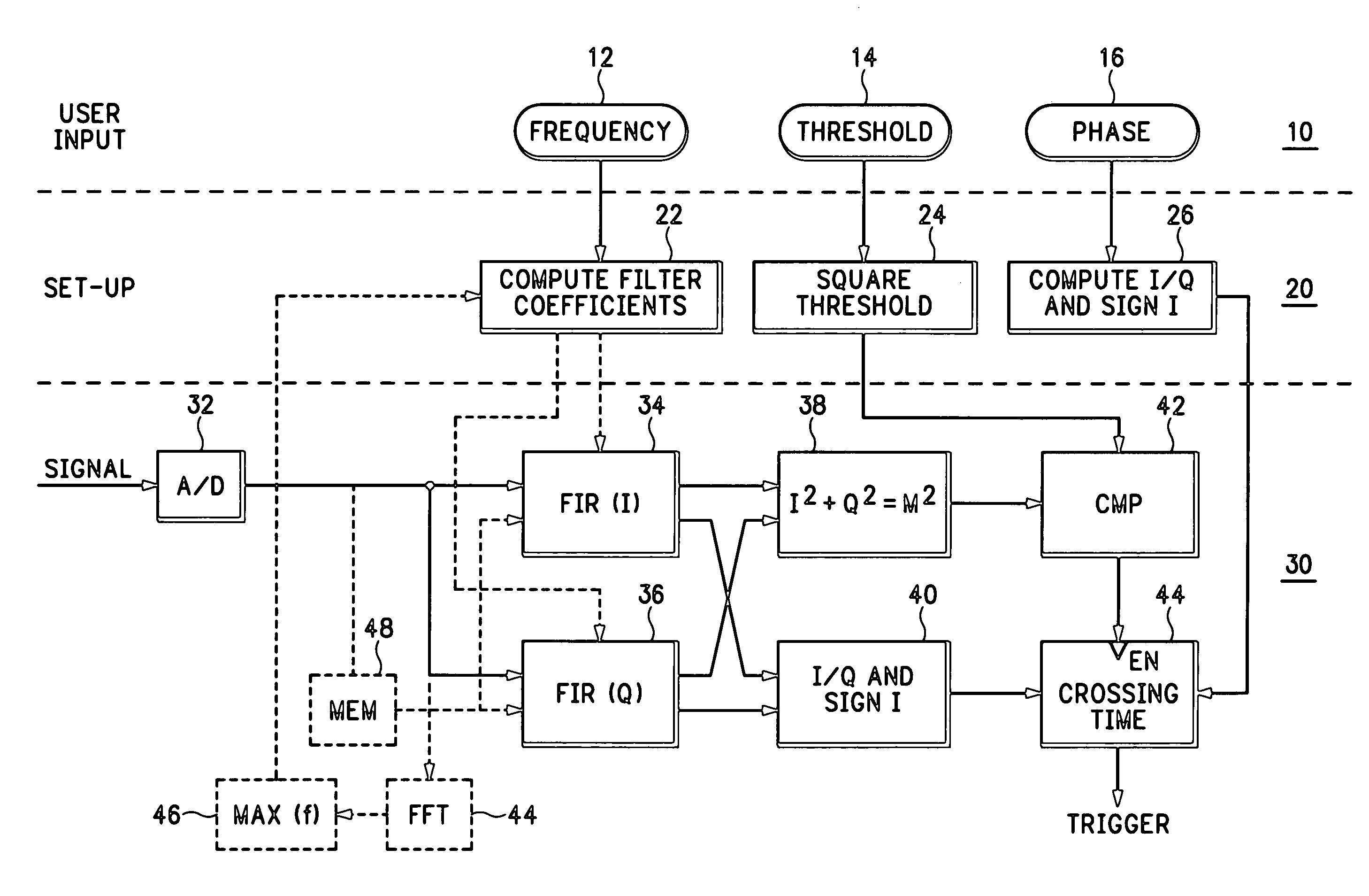
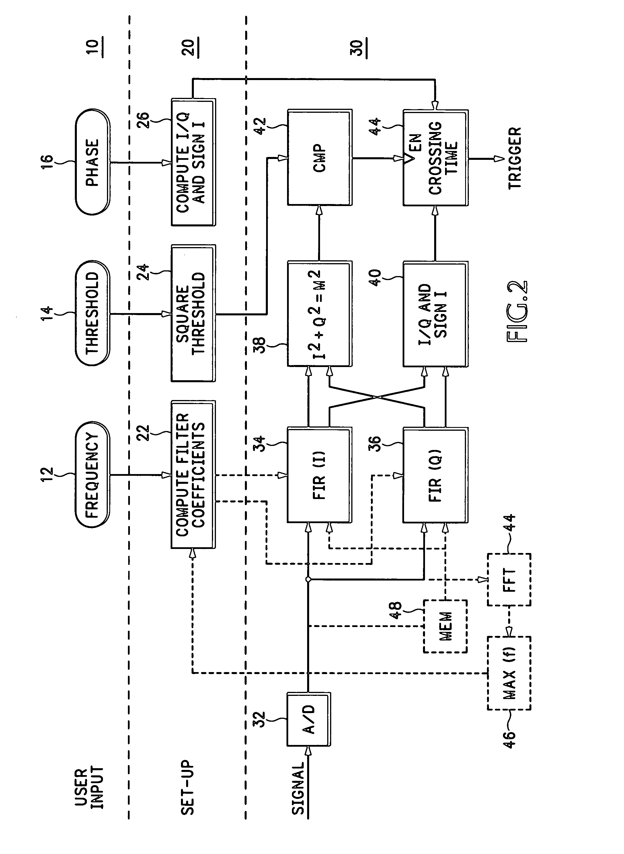
[0014]Referring now to FIG. 2 a realtime spectrum trigger system on a realtime oscilloscope has a user input section 10, such as the user interface shown in FIG. 3, where a user may input a desired trigger frequency 12, magnitude threshold 14 at the trigger frequency and phase crossing 16 at the trigger frequency. Based upon the user inputs a setup section 20 computes filter parameters 22 from the user selected frequency, a squared threshold 24 from the user input magnitude threshold and a quadrature I / Q ratio and sign of the I component from the user selected phase crossing. In the setup section 20 the realtime oscilloscope performs a couple of computations and then uses the computation results in the oscilloscope hardware. A discrete Fourier transform (DFT) is implemented to get a spectrum at the desired trigger frequency.

(DFT)X(k)=Σm=0−(N−1)×(m)WNkm=WN−kNΣm=0−(N−1)×(m)WNkm=Σm=0−(N−1)×(m)WN−k(N−m)  (1)

(Euler)WN−km=ej2πkm / N=cos(2πkm / N)+j sin(2πkm / N)  (2)

where k is determined by a s...


PUM


Abstract

A realtime spectrum trigger system on a realtime oscilloscope considers both the magnitude and phase of an input signal having a periodic component so that successive acquisitions of the input signal are time aligned. A user inputs a frequency, threshold and phase for triggering on the periodic component. Input signal samples are filtered by quadrature filters according to the frequency input to produce quadrature signal components. The square of the magnitude of the input signal is computed from the quadrature signal components, as well as the phase ratio and sign, for comparison with calculated values. When enabled by the magnitude of the input signal, a phase crossing determinator compares the phase ratio and sign with calculated values to determine the phase crossing to generate a trigger, resulting in successive acquisitions of the input signal being in time alignment.

Description

BACKGROUND OF THE INVENTION[0001]The present invention relates to oscilloscope trigger systems, and more particularly to a realtime spectrum trigger system on a realtime oscilloscope.[0002]Realtime oscilloscopes have comprehensive trigger systems to help users obtain stable waveforms for display, quickly capture abnormal behavior, etc. However, these trigger systems are unable to trigger on a periodic signal buried in noise so that subsequent acquisitions of the signal are in time alignment, as shown in FIG. 1. There is no spectrum trigger on realtime oscilloscopes. New realtime spectrum analyzers, such as those manufactured by Tektronix, Inc. of Beaverton, Oreg., have a spectrum trigger that helps to capture frequency events and also display signals in the time domain. However only the magnitude spectrum is considered, while the phase spectrum is not. Phase in the frequency domain corresponds to time delays in the time domain. Time alignment, i.e., phase alignment, is required for ...

Claims


Application Information

Patent Timeline
Patent Type & Authority Applications(United States)
IPC IPC(8): G06F19/00
CPCG01R23/16G01R13/0254G01R13/02
Inventor TAN, KANPICKERD, JOHN J.
Owner TEKTRONIX INC
Why Eureka
Try Eureka