Ct scanning system with interlapping beams

a scanning system and beam technology, applied in the field of acquisition of ct projections, can solve the problems of excessive exposure to x-ray radiation, significant limitation of existing cone beam reconstruction techniques, and inability to acquire the 3d data set one slice at a tim

Inactive Publication Date: 2008-05-01
EIN GAL MOSHE
View PDF3 Cites 33 Cited by
  • Summary
  • Abstract
  • Description
  • Claims
  • Application Information

AI Technical Summary

Problems solved by technology

One drawback to this method is that acquiring the 3D data set one slice at a time is an inherently slow process.
There are other problems with this conventional tomographic technique, such as motion artifacts arising from the fact that the slices cannot be imaged simultaneously, and excessive exposure to x-ray radiation due to overlap of the x-ray projection areas.
A significant limitation of existing cone-beam reconstruction techniques occurs, however, when the projection of the object being imaged is larger than the field-of-view of the detector, which is a quite common situation in both industrial and medical imaging applications.
The resulting image of the field of view of interest is therefore corrupted by data resulting from overlying material.

Method used


Image

  • Ct scanning system with interlapping beams
  • Ct scanning system with interlapping beams
  • Ct scanning system with interlapping beams

Examples


Embodiment Construction

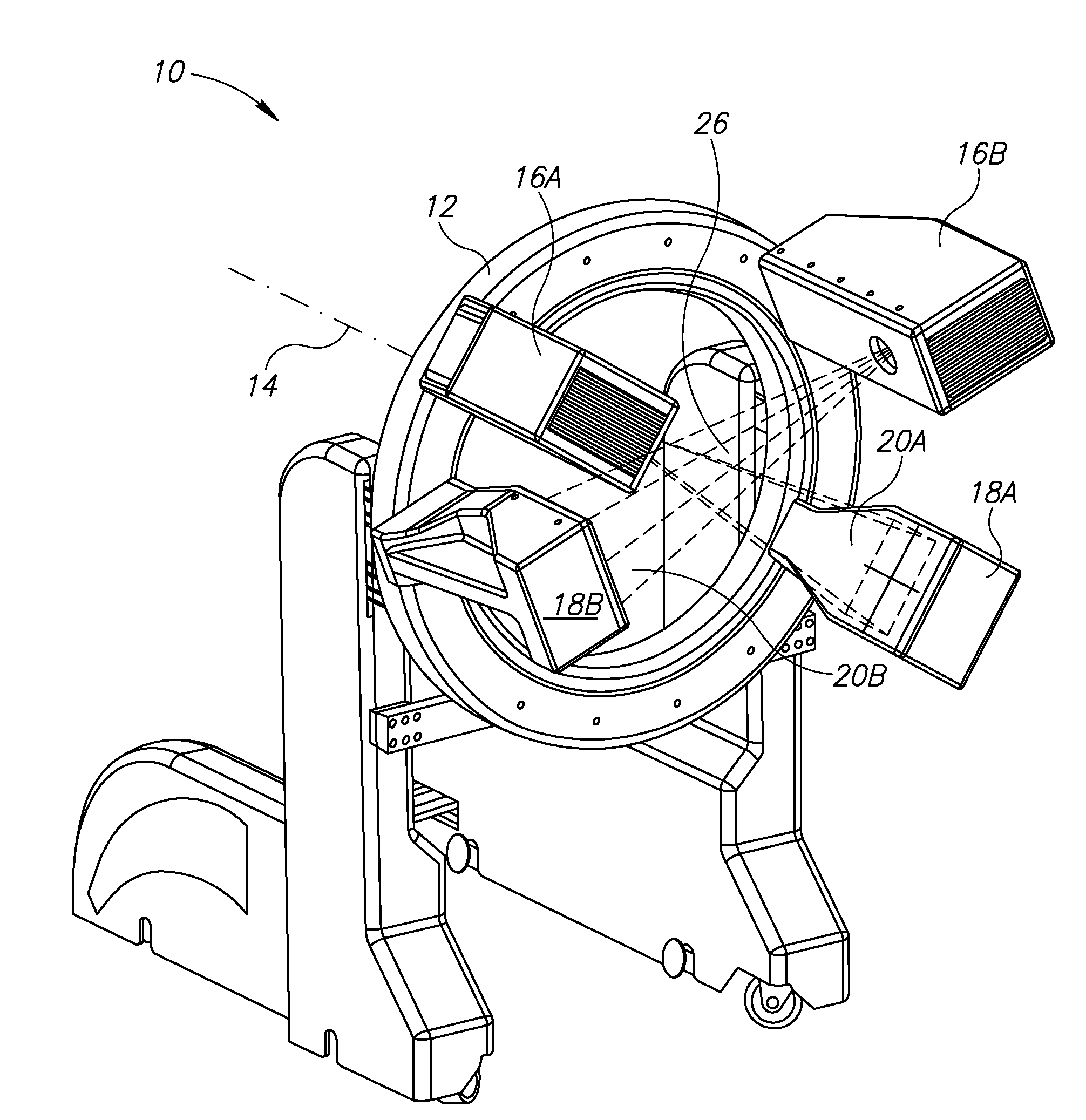
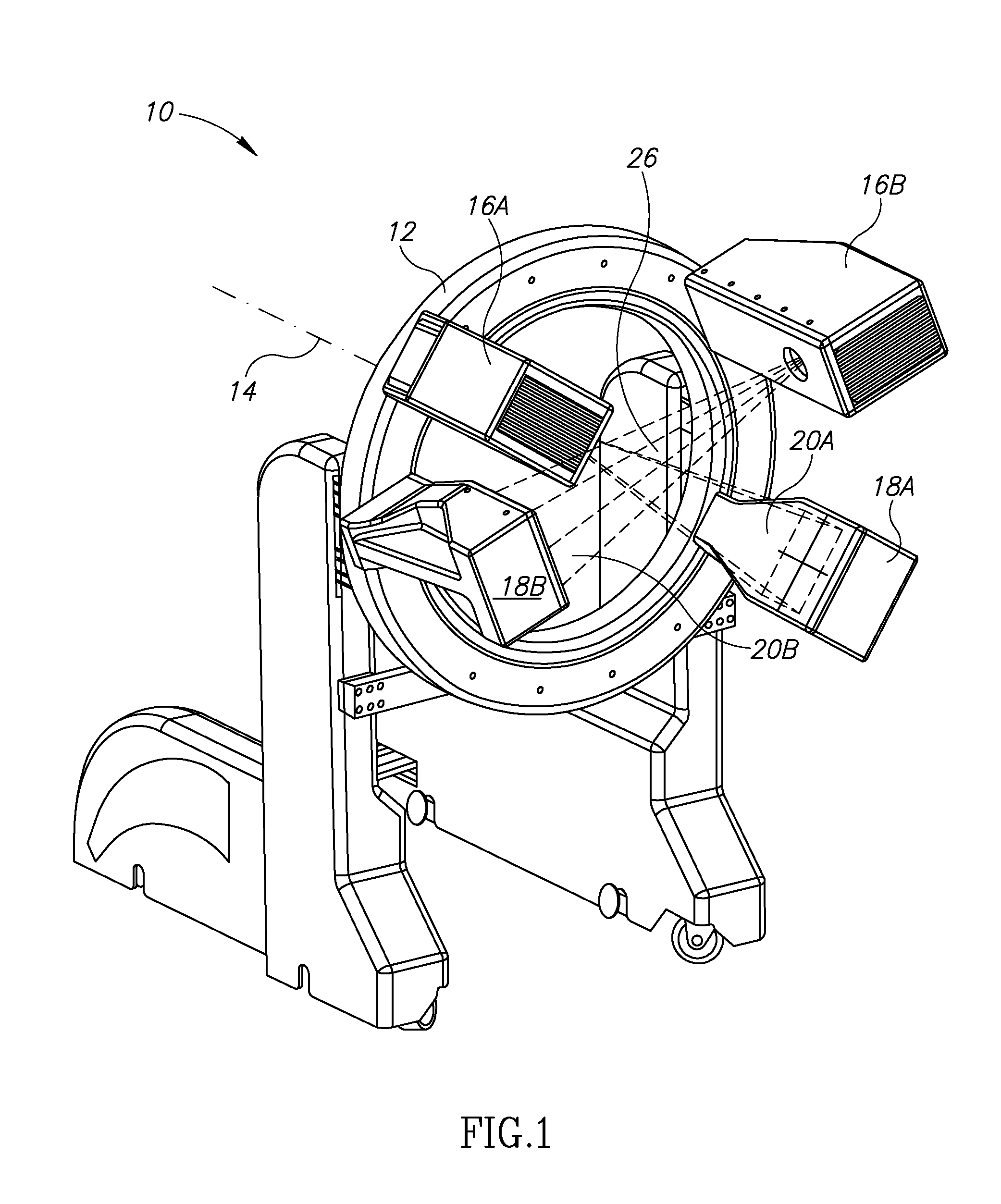
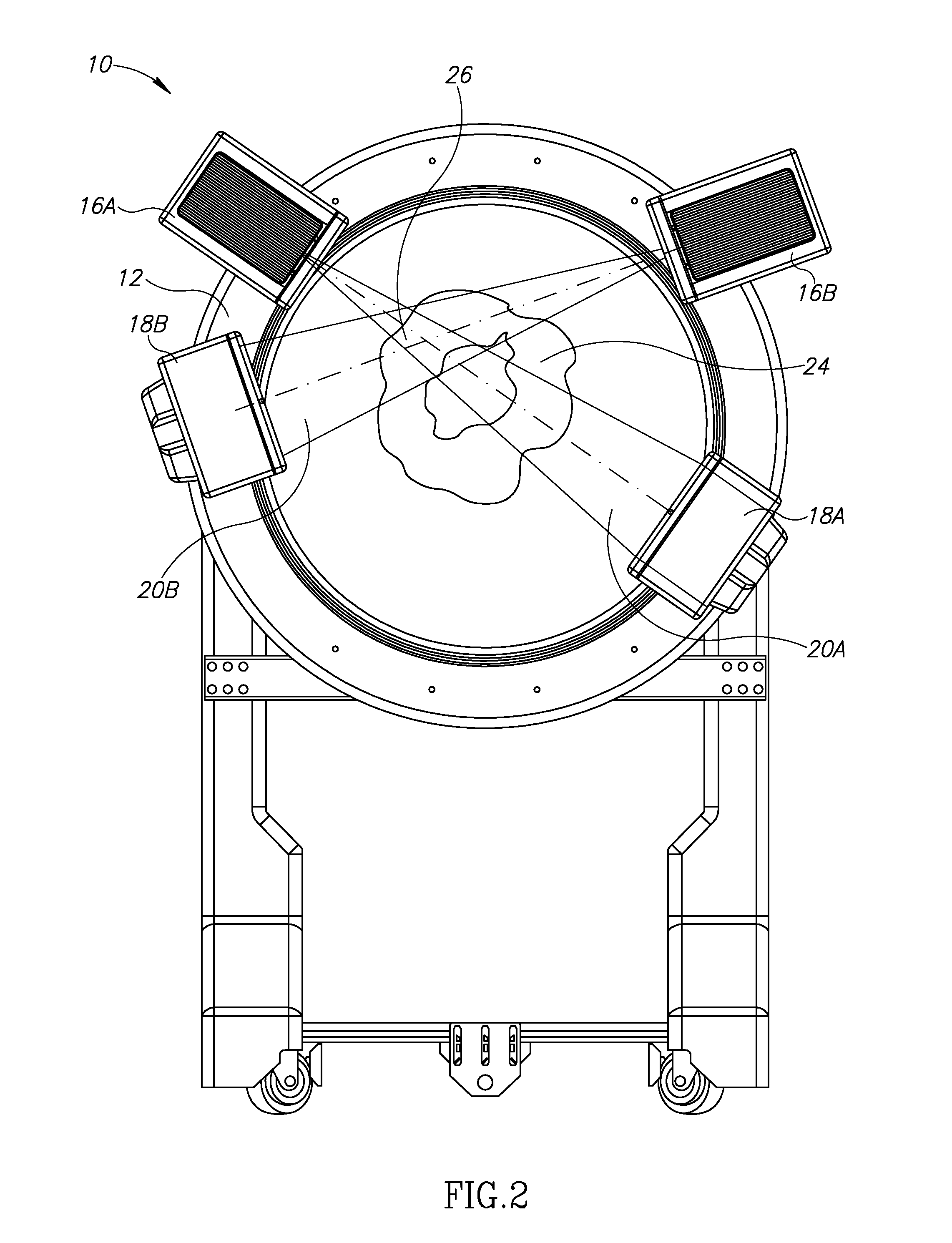
[0016]Reference is now made to FIGS. 1-3, which illustrate CT scanning system 10 constructed and operative in accordance with an embodiment of the present invention.

[0017]CT scanning system 10 may include a gantry 12, which may be rotated about a rotation axis 14. A plurality (two or more) of X-ray imagers may be mounted on gantry 12. Each X-ray imager includes a radiation source (16A and 16B in the figures) and a detector (18A / 18B, respectively). The radiation source 16A / 16B emits a radiation beam (20A or 20B, respectively), and the detector 18A / 18B, which is located a distance from the radiation source 16A / 16B, is positioned to receive the radiation beam 20A / 20B. The radiation source 16A / 16B may be, without limitation, an x-ray cone-beam source (in which case, the radiation beam is a cone beam), and the detector 18A / 18B can be a two-dimensional flat-panel detector array, such as those described in U.S. Pat. No. 7,108,421.

[0018]FIG. 3 illustrates just one example of arranging the r...


PUM

PropertyMeasurementUnit
distanceaaaaaaaaaa
diameteraaaaaaaaaa
radiusaaaaaaaaaa

Abstract

A CT scanning system including a gantry operable to rotate about a rotation axis, and a plurality of X-ray imagers mounted on the gantry, each X-ray imager including a radiation source and a detector, wherein the radiation source is operative to emit a radiation beam (e.g., a cone beam) and the detector is positioned to receive the radiation beam so as to acquire partial projections set of an object through which the beams pass, wherein a union of the partial projections sets forms a projection set sufficient for CT reconstruction of the object.

Description

FIELD OF THE INVENTION[0001]The present invention relates generally to acquisition of CT projections using a multiplicity of beam imagers, such as cone beam imagers.BACKGROUND OF THE INVENTION[0002]In conventional computerized tomography (CT) for both medical and industrial applications, an x-ray fan beam and a linear array detector are employed to achieve two-dimensional axial imaging. The quality of these two-dimensional (2D) images is high, although only a single slice of an object can be imaged at a time. To acquire a three-dimensional (3D) data set, a series of 2D images are sequentially obtained in what is known as the “stack of slices” technique. One drawback to this method is that acquiring the 3D data set one slice at a time is an inherently slow process. There are other problems with this conventional tomographic technique, such as motion artifacts arising from the fact that the slices cannot be imaged simultaneously, and excessive exposure to x-ray radiation due to overla...

Claims


Application Information

Patent Timeline
Patent Type & Authority Applications(United States)
IPC IPC(8): A61B6/00G01N23/00G21K1/12H05G1/60
CPCA61B6/032A61B6/4014A61N2005/1063A61N5/10A61B6/4405Y10S378/901
Inventor EIN-GAL, MOSHE
Owner EIN GAL MOSHE
Why Eureka
Try Eureka