Guiding device for saw blade of band saw

Active Publication Date: 2008-05-15
OAV EQUIP & TOOLS
View PDF29 Cites 11 Cited by
  • Summary
  • Abstract
  • Description
  • Claims
  • Application Information

AI Technical Summary

Benefits of technology

[0008]The present invention has been accomplished under the circumstances in view. It is therefore one objective of the present invention to p

Problems solved by technology

1. The rollers 724 and 733 are directly contacted with the saw blade 74. When the saw blade 74 is driven to move by the motor (not shown), a friction is produced between the saw blade 74 and the rollers 724 and 733. Because the rollers 724 and 733 are metal members, the surfaces of the rollers 724 and 733 might wear out quickly with the use of the metal rol

Method used


Image

  • Guiding device for saw blade of band saw
  • Guiding device for saw blade of band saw
  • Guiding device for saw blade of band saw

Examples


Embodiment Construction

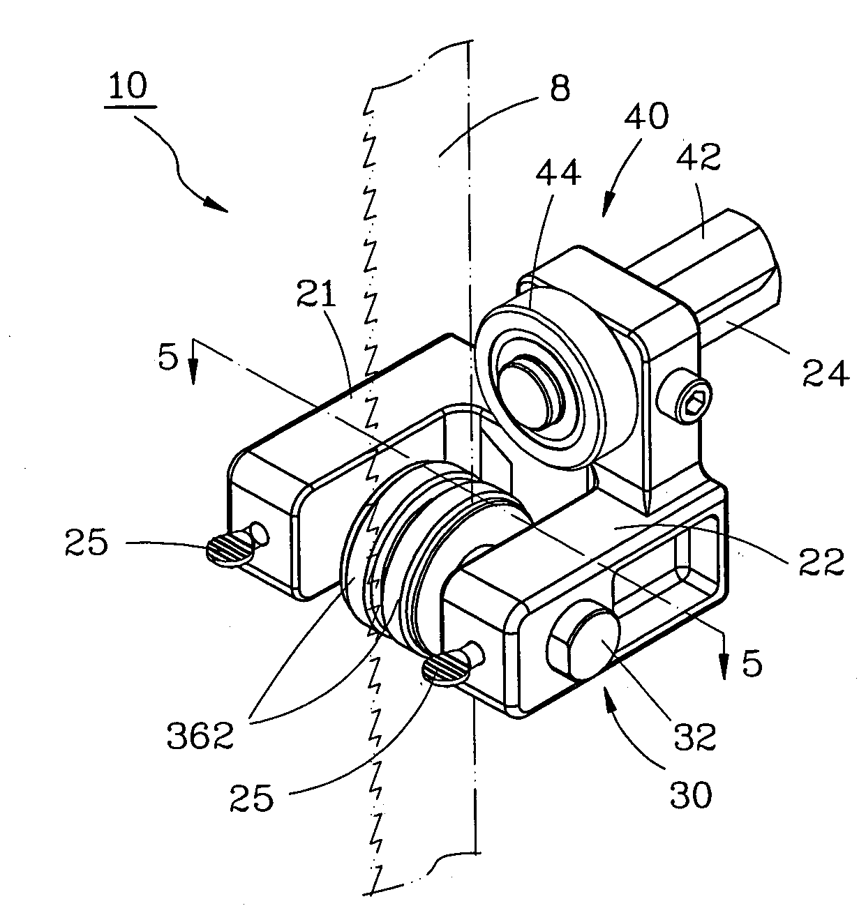
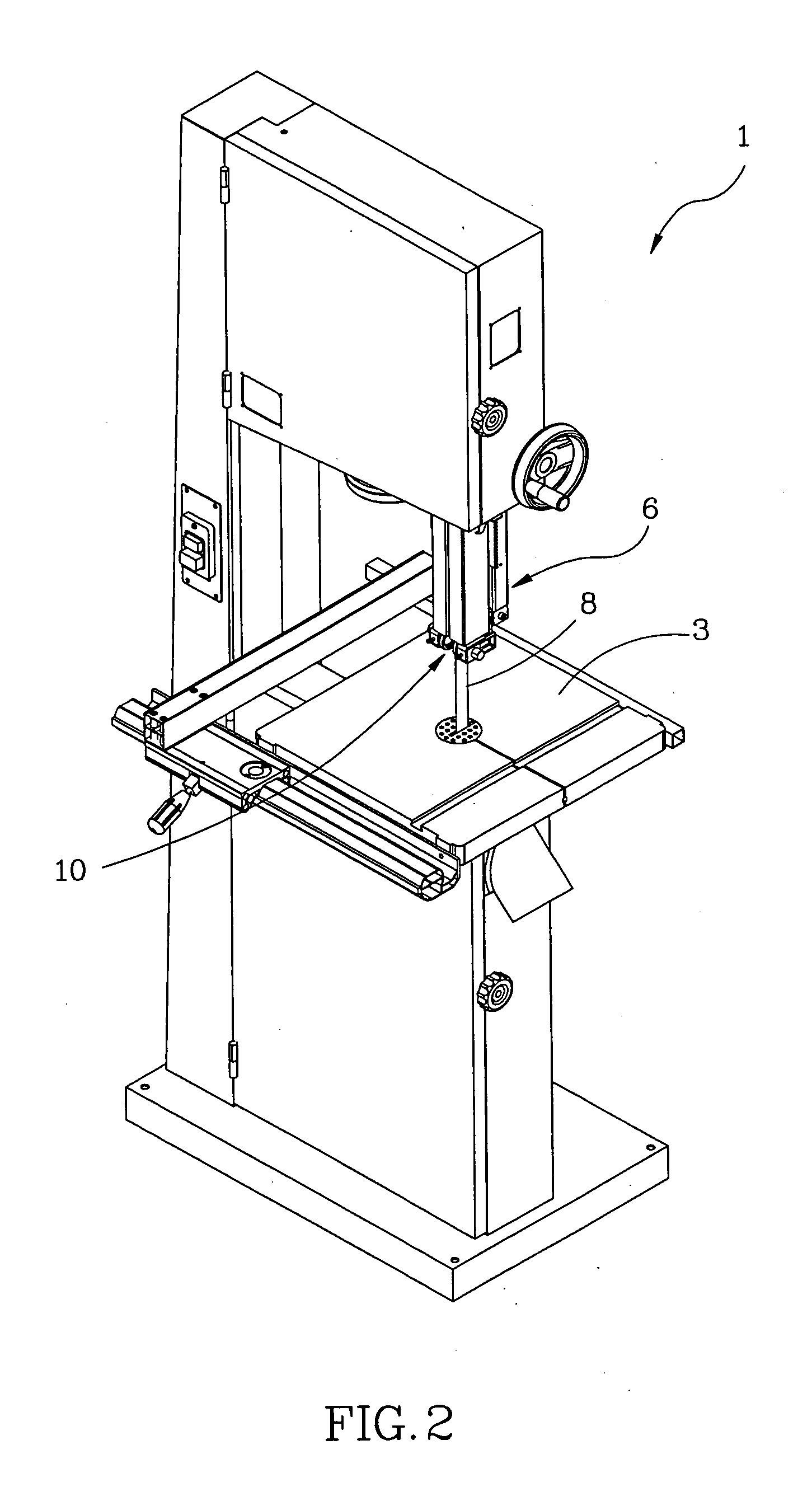
[0019]As shown in FIGS. 2 and 3, a saw blade guiding device 10 is used for installation in a band saw 1 above a table 3 for guiding movement of a saw blade 8. The saw blade guiding device 10 comprises a holder base 20, two saw blade guiding units 30, and a saw blade urging unit 40.

[0020]The holder base 20 is a substantially U-shaped block having a vertically extending base portion 23, two horizontal supporting arms 21 and 22 extending from two opposite lateral sides of the base portion 23 and arranged in parallel, and a horizontal mounting rod 24 perpendicularly backwardly extending from the back side of the vertically extending base portion 23 in reversed direction relative to the supporting arms 21 and 22 for fastening to a lifting mechanism 6 of the band saw 1. The supporting arms 21 and 22 each have a transverse through hole 212 or 222 and a front screw hole 214 or 224 in communication with the respective through hole 212 or 222. Two screw bolts 25 are respectively partially thr...


PUM


Abstract

A guiding device for guiding movement of a saw blade of a band saw includes a holder base and two saw blade guiding units. The holder base includes a base portion for mounting to the band saw, and two parallel supporting arms. Each of the saw blade guiding units has a sleeve fastened to a transversely extending through hole of one of the supporting arms, a ball rotatably received in the sleeve, and a wheel having a metal wheel shaft with one end inserted into the sleeve and stopped at the ball, and a wheel body made of ceramic material and connected to the other end of the wheel shaft for stopping against one lateral side of the saw blade.

Description

BACKGROUND OF THE INVENTION[0001]1. Field of the Invention[0002]The present invention relates to a band saw and more specifically, to a device for guiding a saw blade of the band saw.[0003]2. Description of the Related Art[0004]A conventional band saw generally uses a saw blade guiding device to guide movement of the saw blade. FIG. 1 shows a saw blade guiding device 70 according to the prior art. According to this design, the saw blade guiding device 70 comprises a mounting base 71 affixed to a lifting mechanism of a band saw (not shown), a saw blade urging unit 72 provided at the front side of the mounting base 71 near the top, and a saw blade guiding unit 73 provided at the front side of the mounting base 71 near the bottom. The saw blade urging unit 72 comprises a shaft 722 fixedly connected to the mounting base 71, and a roller 724 rotatably supported on the shaft 722 and disposed in contact with the back side of the saw blade 74 opposite to the cutting teeth of the saw blade 7...

Claims


Application Information

Patent Timeline
IPC IPC(8): B26D5/00
CPCB23D55/082Y10T83/7264Y10T83/8884Y10T83/8889
Inventor WANG, JACKY
Owner OAV EQUIP & TOOLS
Why Eureka
Try Eureka