Electronic Thermometer with Selectable Modes

Active Publication Date: 2008-05-15
CARDINAL HEALTH IRELAND UNLTD
View PDF99 Cites 24 Cited by
  • Summary
  • Abstract
  • Description
  • Claims
  • Application Information

AI Technical Summary

Benefits of technology

[0009]The present invention is embodied in a prediction type electronic thermometer configured to allow user selection of the desired response time of the thermometer and the desired precision of the temperature readings. In one exemplary embodiment of the present invention, the application of a particular prediction algorithm prov

Problems solved by technology

Despite the response time improvements over glass thermometers, some known electronic thermometers have unacceptably long response time.
The thermal mass of the probe and the sensor components may take several minutes to reach the actual body temperature of the patient being measured.
Both of these techniques improve response time somewhat but still allow time to be wasted while heat from the patient flows to the thermal mass of the probe instead of the temperature sensors.
Even though thermometers have been improved by various methods in the prior art, disadvantages of the prior art t

Method used


Image

  • Electronic Thermometer with Selectable Modes
  • Electronic Thermometer with Selectable Modes
  • Electronic Thermometer with Selectable Modes

Examples


Example

[0018]Corresponding reference characters indicate corresponding parts throughout the several views of the drawings.

DETAILED DESCRIPTION OF THE INVENTION

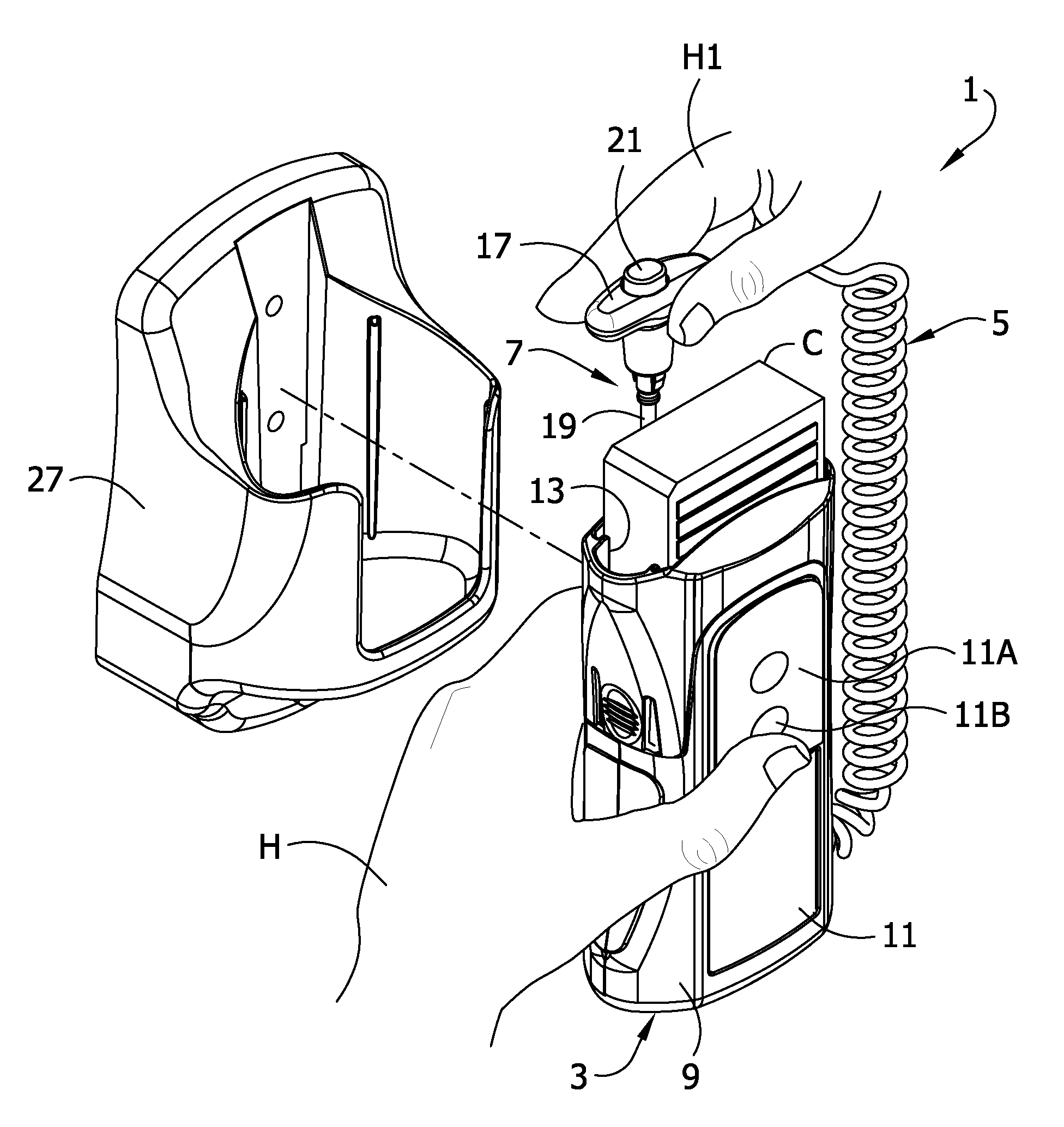
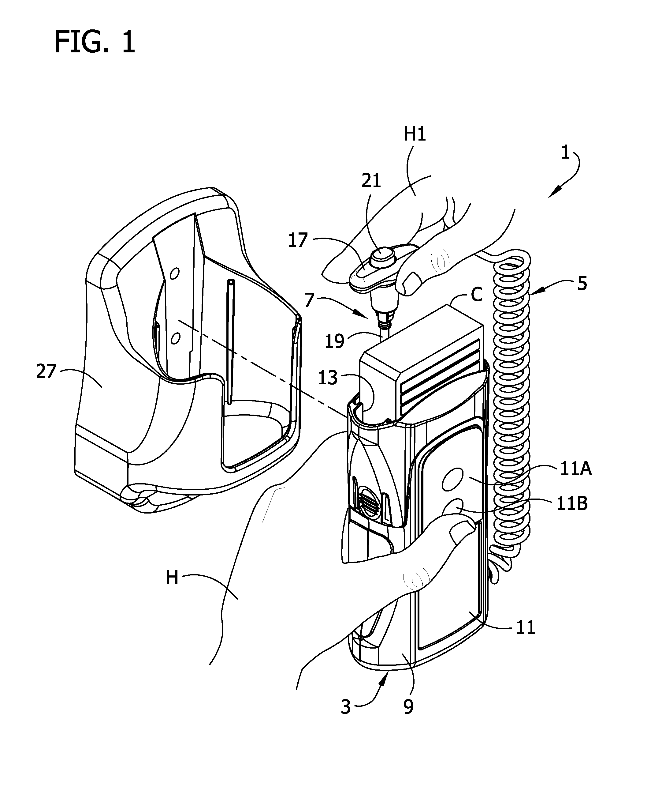
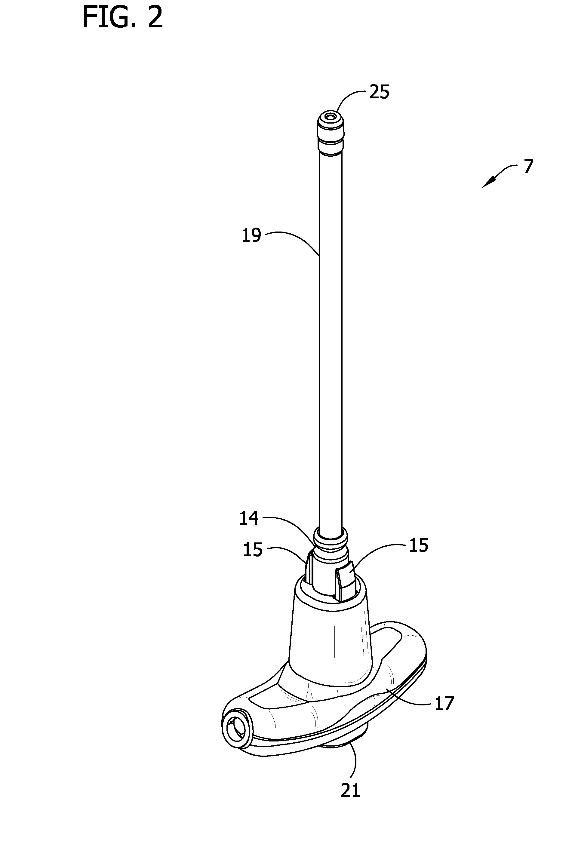
[0019]Referring now to the drawings and in particular to FIGS. 1 and 2, an electronic thermometer constructed according to the principles of the present invention is indicated generally at 1. The electronic thermometer comprises a temperature calculating unit, indicated generally at 3, that is sized and shaped to be held comfortably in the hand H. The calculating unit 3 (broadly, “a base unit”) is connected by a helical cord 5 to a probe 7 (the reference numerals indicating their subjects generally). The probe 7 is constructed for contacting the subject (e.g., a patient, not shown) and sending signals to the calculating unit 3 representative of the temperature. The calculating unit 3 receives the signals from the probe 7 and uses them to calculate the temperature. Suitable circuitry for performing these calculations is contained with...


PUM


Abstract

An electronic thermometer is configured for selectable predictive modes based upon the same predictive algorithm. A mode selector is adapted for user selection between several modes of operation of the thermometer. Each mode of operation utilizes the same predictive algorithm for estimating the temperature of the subject before the thermometer reaches full equilibrium. Different modes offer users a selection for striking the appropriate balance between response time and precision, based upon user preferences and needs.

Description

FIELD OF THE INVENTION[0001]The invention pertains to the field of electronic thermometers and more particularly the field of fast response electronic thermometers employing a sensor probe.BACKGROUND OF THE INVENTION[0002]Electronic thermometers are widely used in the healthcare field for measuring patient's body temperature. Typical electronic thermometers have the form of a probe with an elongated shaft portion. Electronic temperature sensors such as thermistors or other temperature-sensitive elements are contained within the shaft portion. Additional electronics connected to the electronic sensor components may be contained within a base unit connected by wire to the shaft portion or may be contained within a handle of the shaft portion, for example. Electronic components receive input from the sensor components to compute the patient's temperature. The temperature is then typically displayed on a visual output device such as a seven, or fourteen, segment numerical display device...

Claims


Application Information

Patent Timeline
IPC IPC(8): G01K7/00
CPCG01K13/002G01K7/42G01K13/20
Inventor BISCH, MICHAEL E.GIERER, JOSEPH T.
Owner CARDINAL HEALTH IRELAND UNLTD
Why Eureka
Try Eureka