Liquid crystal panel, liquid crystal display device and method for improving liquid crystal rotation obstacle

Active Publication Date: 2018-08-02
WUHAN CHINA STAR OPTOELECTRONICS TECH CO LTD
2 Cites 3 Cited by

AI-Extracted Technical Summary

Problems solved by technology

However, since the liquid crystal molecules are rod-like structures, the direction of the liquid crystal standing is not fixed, the liquid crystal may stand up starting from one end or from the other end.
Therefore, during the process of th...

Method used

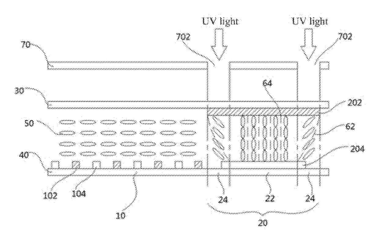
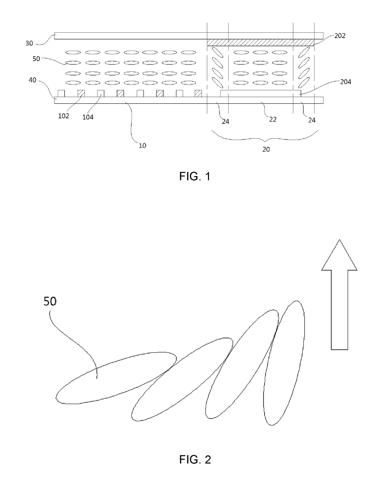
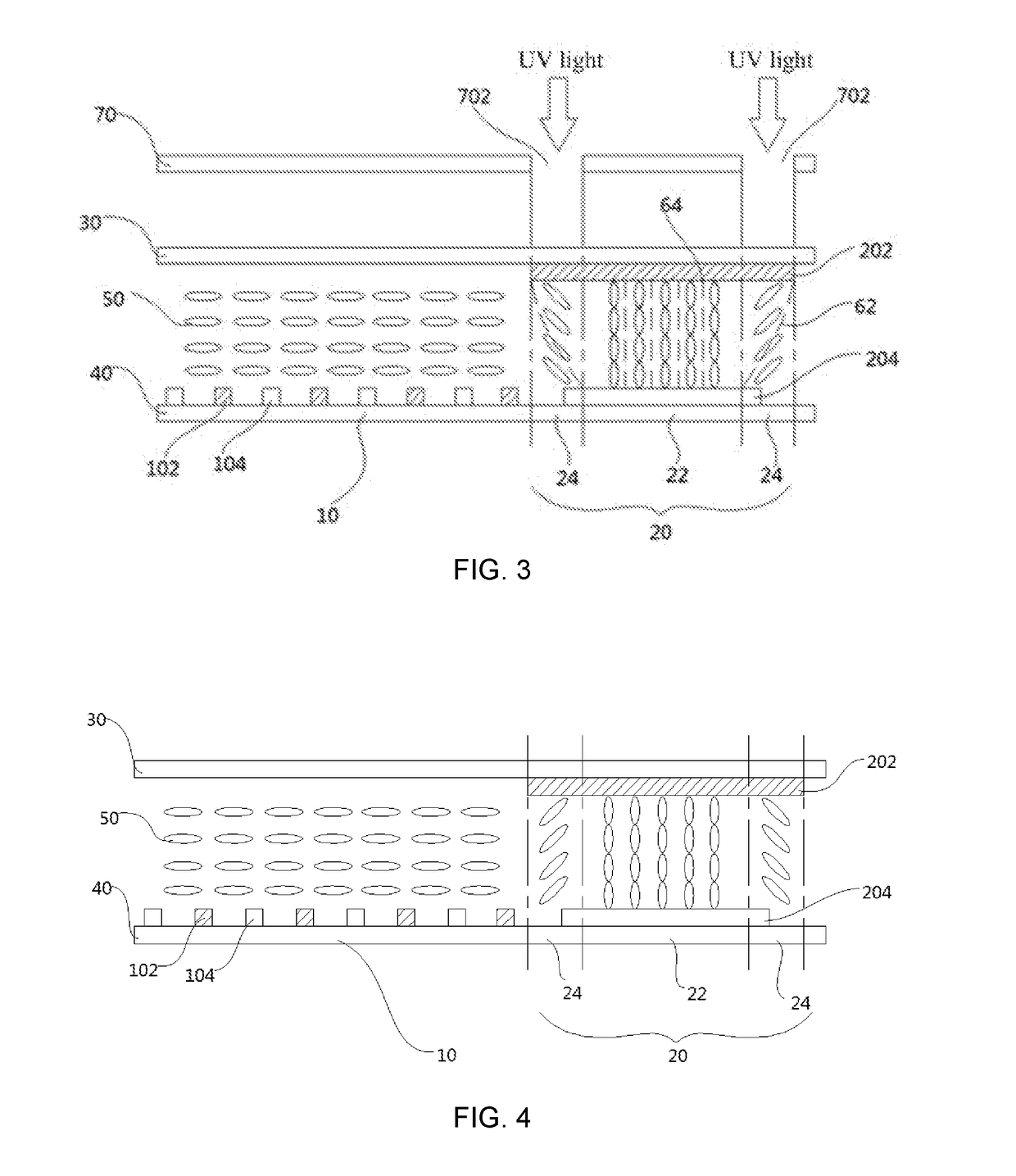
[0031]FIG. 1 is a schematic structural view of a viewing angle switchable liquid crystal panel according to a first embodiment of the invention. As illustrated in the figure, the viewing angle switchable liquid crystal panel includes an upper substrate 30, a lower substrate 40 and liquid crystal molecules 50 arranged therebetween. The liquid crystal molecules are a positive liquid crystal. A pixel unit of the liquid crystal panel includes a main pixel area 10 and a sub pixel area 20. On the lower substrate 40 of the main pixel area 10, pixel electrodes 102 and common electrodes 104 are alternately arranged; the main pixel area is horizontal orientation/alignment, the liquid crystal molecules 50 in the main pixel area only can rotate in a plane parallel to the upper substrate 30 and the lower substrate 40, and therefore is at an in-plane switching (IPS) mode. When there is no voltage is applied, the liquid crystal molecules 50 in the main pixel area 10 completely are not rotated, since polarization directions of front and rear two polarizers of the liquid crystal panel are perpendicular to each other, the polarization direction of a backlight source provided by a backlight module of the display device and passing through the rear polarizer would not be changed by the liquid crystal molecules 50 and therefore cannot pass through the front polarizer, so that the liquid crystal panel can only display black. When a voltage is applied, the liquid crystal molecules are rotated, the horizontal polarized light is converted to a vertical polarized light, and thus the backlight rays can pass through, the amount of converted polarized light can be controlled by changing the magnitude of an electric field applied between the two sides of the liquid crystal molecules 50 and therefore the purpose of controlling light rays is achieved. The IPS mode of the main pixel area improves the viewing angle in the manner of in-plane switching, uses cha...

Benefits of technology

[0022]Efficacy can be achieved by the invention is as follows: the lengths of the viewing angle upper and lower electrodes are different from each other, the portion(s) corresponding to the length difference generate(s) an oblique electric field to make some liquid crystal molecules to be obliquely oriented, and the liquid crystal molecules then are irradiated by UV light to form an initial pretilt angle; after that, when applying a voltage onto the v...

Abstract

A liquid crystal panel includes oppositely disposed upper and lower substrates having a liquid crystal disposed therebetween. A surface of the upper substrate and a surface of the lower substrate are formed with viewing angle upper and lower electrodes respectively, and a length of the lower electrode is shorter than that of the upper electrode. The upper electrode completely covers projection of the lower electrode on the upper substrate. A region between the upper and lower electrodes includes adjacent main body region and pretilt region, the pretilt region is corresponding to edges of the upper and lower electrodes, and portions of the upper and lower electrodes corresponding to the main body region have same sizes. A liquid crystal display device and a method for improving liquid crystal rotation obstacle further are provided. Accordingly, a response time of viewing angle switching is reduced and viewing angle symmetry is improved.

Application Domain

Technology Topic

Image

  • Liquid crystal panel, liquid crystal display device and method for improving liquid crystal rotation obstacle
  • Liquid crystal panel, liquid crystal display device and method for improving liquid crystal rotation obstacle
  • Liquid crystal panel, liquid crystal display device and method for improving liquid crystal rotation obstacle

Examples

  • Experimental program(1)

Example

[0034]A method for improving liquid crystal rotation obstacle according to the first embodiment of the invention specifically includes steps as follows.
[0035]Step one: applying a voltage onto the viewing angle upper electrode 202 and the viewing angle lower electrode 204 in the sub pixel area 20. Since the length of the viewing angle lower electrode 204 is shorter than the viewing angle upper electrode 202, the pretilt regions 24 at the two ends of the sub pixel area 20 generate an oblique electric field, the positive liquid crystal molecules 50 with an initial state of horizontal lying are rotated to a state parallel to oblique electric field lines 62 under the effect of the oblique electric field, the main body region 22 in the middle of the sub pixel area 20 generates a vertical electric field to make the liquid crystal molecules therein to be rotated to a vertical state parallel to vertical electric field lines 64.
[0036]The oblique electric field in the pretilt regions 24 makes the liquid crystal molecules 50 in such regions be obliquely oriented/aligned, which facilitates subsequent fixing of initial pretilt angle α.
[0037]Step two: as shown in FIG. 3, providing a masking plate 70. The masking plate 70 is formed with two gaps 702 only corresponding to the pretilt regions 24. The gaps 702 are irradiated by UV light for making the obliquely aligned liquid crystal molecules in the pretilt regions 24 to form an initial pretilt angle.
[0038]The method of using the masking plate to cover and using the UV light to irradiate can relatively simply to obtain the initial pre-tilt angle α. The magnitude of the initial pretilt angle α is determined by oblique angles of the oblique electric field lines 62, i.e., is related to the length difference of the viewing angle upper and lower electrodes and the magnitude of the applied voltage.
[0039]Step three: stopping applying the voltage. The liquid crystal molecules 50 in the main body region 22 restore to the initial horizontal lying state, the liquid crystal molecules 50 in the pretilt regions 24 maintain the initial pretilt angle α. After that, when applying a voltage onto the viewing angle upper electrode 202 and the viewing angle lower electrode 204, the liquid crystal molecules 50 in the pretilt regions 24 would drive adjacent liquid crystal molecules 50 in the main body region 22 to orderly rotate along one direction.
[0040]The lengths of the viewing angle upper electrode 202 and the viewing angle lower electrode 204 are not equal, the portion corresponding to the length difference generates an oblique electric field to make some liquid crystal molecules to be obliquely oriented, and the liquid crystal molecules 50 would form the initial pretilt angle α after UV light irradiation. After that, when applying an voltage onto the viewing angle upper electrode 202 and the viewing angle lower electrode 204, the liquid crystal molecules 50 in the pretilt regions 24 would drive the liquid crystal molecules 50 in the adjacent main body region 22 to rotate, so that the liquid crystal molecules 50 in the sub pixel area 20 can orderly rotate starting from a same end, the “fight” phenomenon of liquid crystal molecules 50 is avoided, and therefore response time of viewing angle switching is reduced and viewing angle symmetry after the viewing angle switching is improved.
[0041]FIG. 4 is a schematic structural view of a viewing angle switchable liquid crystal panel according to a second embodiment of the invention. As shown in the figure, a difference of the second embodiment from the first embodiment is that: the liquid crystal molecules 50 is a negative liquid crystal. A working principle of the main body area 10 is the same as that in the first embodiment; in the sub pixel area 20, an initial state of the liquid crystal molecules 50 of the main body region 22 is at a vertical/upright state, the sub pixel area 20 leaks light and thus does not display an image, the liquid crystal panel is at a narrow viewing angle display mode, an initial state of the liquid crystal molecules 50 of the pretilt regions 24 is an oblique alignment with an initial pretilt angle α, the magnitude of the pretilt angle α is determined by a length difference between the viewing angle upper electrode 202 and the viewing angle lower electrode 204 and a magnitude of an applied voltage during fixing the initial pretilt angle α. In conjunction with FIG. 5, after a voltage is applied, the liquid crystal molecules 50 in the pretilt regions 24 are rotated starting from the oblique alignment to a horizontal lying state and meanwhile drive the liquid crystal molecules 50 in the adjacent main body region 22 to rotate along a same direction from the vertical state to a horizontal lying state, the sub pixel area 20 displays an image, and the liquid crystal panel is at a wide viewing angle display mode.
[0042]Steps of a method for improving liquid crystal rotation obstacle according to the second embodiment are similar to that of the first embodiment, as shown in FIG. 6, a difference is that the liquid crystal molecules 50 in the second embodiment are a negative liquid crystal, the initial state of the liquid crystal molecules 50 in the sub pixel area 20 is the vertical state, after the viewing angle upper electrode 202 and the viewing angle lower electrode 204 are applied with a voltage, the liquid crystal molecules 50 in the main body region 22 are rotated to a horizontal lying state perpendicular to the vertical electric field lines 64 from the vertical state, the oblique electric field in the pretilt regions 24 makes the liquid crystal molecules 50 in such regions to be obliquely aligned along a direction perpendicular to the oblique electric field lines, and then a manner of using a UV light to irradiate gaps of a masking plate is adopted to obtain the initial pretilt angle α. The viewing angle upper electrode 202 and the viewing angle lower electrode 204 are at a narrow viewing angle mode when no voltage is applied therebetween, and then switched to a wide viewing angle mode after a voltage is applied therebetween, because the liquid crystal molecules 50 orderly rotate along a same direction, the “fight” phenomenon among the liquid crystal molecules 50 is avoided, the response time of viewing angle switching is reduced and the viewing angle symmetry after the viewing angle switching is improved consequently.
[0043]While the invention has been described in terms of what is presently considered to be the most practical and preferred embodiment, it is to be understood that the invention needs not be limited to the disclosed embodiment. On the contrary, it is intended to cover various modifications and similar arrangements included within the spirit and scope of the appended claims which are to be accorded with the broadest interpretation so as to encompass all such modifications and similar structures.

PUM

no PUM

Description & Claims & Application Information

We can also present the details of the Description, Claims and Application information to help users get a comprehensive understanding of the technical details of the patent, such as background art, summary of invention, brief description of drawings, description of embodiments, and other original content. On the other hand, users can also determine the specific scope of protection of the technology through the list of claims; as well as understand the changes in the life cycle of the technology with the presentation of the patent timeline. Login to view more.

Similar technology patents

Aggregation handling

ActiveUS10318446B2Reduce response timeEfficiently solveProgram controlReal-time computingMethod access
Owner:IBM CORP

Software network behavior analysis and identification system

ActiveUS20150096019A1Reduce response timeCost reductionMemory loss protectionError detection/correctionNetwork behaviorSoftware network
Owner:THE BOEING CO

Read-ahead on signed connections with unsigning, inline, transparent proxies

ActiveUS20170041431A1Reduce response timeCode conversionTransmissionClient-sideServer agent
Owner:SONICWALL US HLDG INC

Optical touch panel device and recording medium

InactiveUS20150097813A1Control power consumptionReduce response timeInput/output processes for data processingOptical pathTouch panel
Owner:SHARP KK

Classification and recommendation of technical efficacy words

  • Improvement of switch
  • Reduce response time

Incremental erasing of flash memory to improve system performance

InactiveUS20060053247A1Reduce response timeRead-only memoriesMemory systemsMemory controllerFlash memory controller
Owner:TEXAS INSTR INC

LCD overdrive table triangular interpolation

InactiveUS20050146495A1Reduce response timeStatic indicating devicesFrame timeAlgorithm
Owner:GENESIS MICROCHIP

Electronic Thermometer with Selectable Modes

ActiveUS20080112461A1Reduce response timeIncrease precisionRadiation pyrometryThermometers using electric/magnetic elementsOperation modePrediction algorithms
Owner:CARDINAL HEALTH IRELAND UNLTD
Why Eureka
Try Eureka