Electric field effect read/write head, method of manufacturing the same, and electric field effect storage apparatus having the same

Inactive Publication Date: 2009-01-01
SAMSUNG ELECTRONICS CO LTD
4 Cites 2 Cited by

AI-Extracted Technical Summary

Problems solved by technology

Accordingly, when moving images are displayed, motion blur phenomena such as afterimages occur, so image quality degrades.
Howe...

Method used

[0038]The time that the first pulse signal and the second pulse signal overlap is the time that a response time is sufficiently completed in a single frame. Accordingly, impulsive driving is performed using the backlight scanning method or the black frame inserting method after the time that the first pulse signal and the second pulse signal overlap, so that generation of double edges can be prevented when frames are shifted.
[0050]Subsequently, the impulsive driving unit 220 performs impulsive driving from the time the first pulse signal and the second pulse signal overlap until the following first pulse signal appears (S430). More specifically, the imp...

Benefits of technology

[0014]An aspect of the present invention provides a display apparatus which reduces a response time by multiple speed driving of input images and performs s...

Abstract

An image display apparatus and method which remove double edges are provided. The image display apparatus includes a first driving unit which generates pulse signals indicating the beginning of each of a plurality of frames which constitute an image signal reproduced by adjusting a frame rate of an image signal, a second driving unit which performs impulsive driving while the pulse signals are generated, and a third driving unit which displays the frames received after the impulsive driving on a display.

Application Domain

Static indicating devicesDifferential synchronisation source locking

Technology Topic

Image

  • Electric field effect read/write head, method of manufacturing the same, and electric field effect storage apparatus having the same
  • Electric field effect read/write head, method of manufacturing the same, and electric field effect storage apparatus having the same
  • Electric field effect read/write head, method of manufacturing the same, and electric field effect storage apparatus having the same

Examples

  • Experimental program(1)

Example

[0025]Certain exemplary embodiments of the present invention will now be described in greater detail with reference to the accompanying drawings.
[0026]In the following description, like drawing reference numerals are used for like elements, even in different drawings. The matters defined in the description, such as detailed construction and elements, are provided to assist in a comprehensive understanding of the invention. However, the present invention can be practiced without those specifically defined matters. Also, well-known functions or constructions are not described in detail since they would obscure the invention with unnecessary detail.
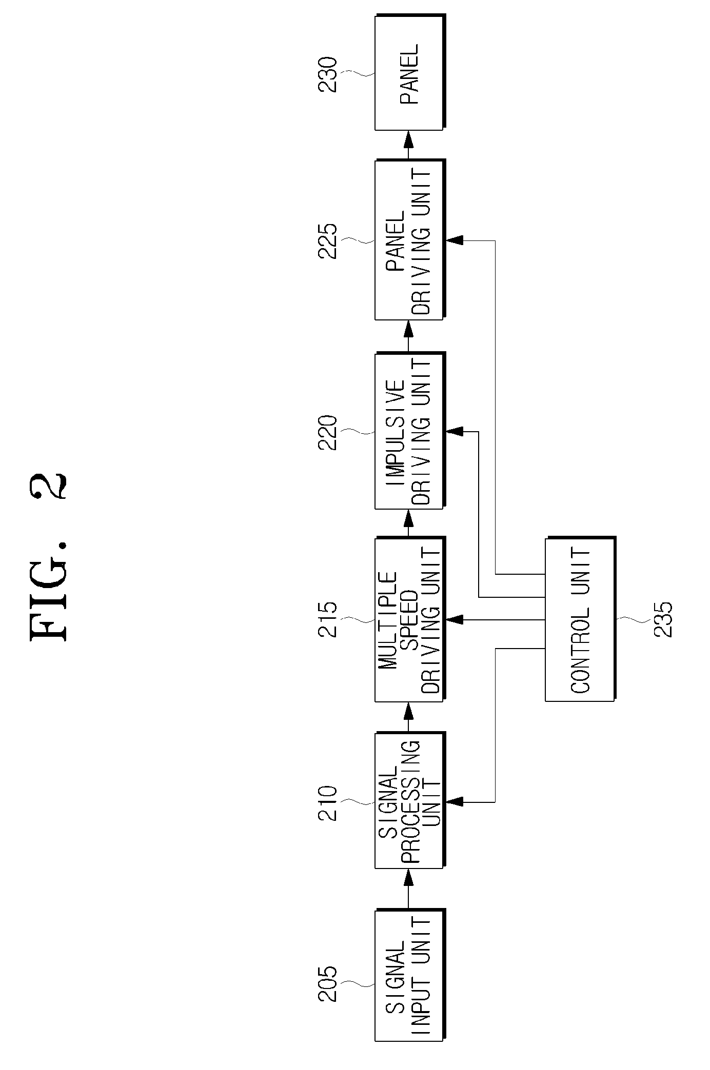
[0027]FIG. 2 is a block diagram of an image display apparatus according to an exemplary embodiment of the present invention.
[0028]In FIG. 2, the image display apparatus includes a signal input unit 205, a signal processing unit 210, a multiple speed driving unit 215, an impulsive driving unit 220, a panel driving unit 225, a panel 230, and a control unit 235.
[0029]The signal input unit 205 receives an image signal from an external device (not shown) through a tuner or an input terminal.
[0030]The signal processing unit 210 receives the image signal from the signal input unit 205 and processes the image signal to be displayed on the panel 230 under the control of the control unit 235.
[0031]The multiple speed driving unit 215 adjusts the frame rate of the processed image signal and thereby generates a first pulse signal indicating the beginning of the frames constituting the adjusted image signal and a second pulse signal indicating the beginning of the frames added to adjust the frame rate.
[0032]In greater detail, the multiple speed driving unit 215 multiplies the frequency of an input image signal by a predetermined number, so the same frames are repeated the predetermined number of times. In addition, the multiple speed driving unit 215 generates a first pulse signal indicating the beginning of all the frames constituting the frame-rate-adjusted image signal and a second pulse signal indicating the beginning of all the frames added to adjust the frame rate.
[0033]For example, if the multiple speed driving unit 215 performs double speed driving of an image input at a frequency of 60 Hz, the frequency of the image signal is adjusted to 120 Hz and a single frame becomes two frames. A first pulse signal indicating the beginning of the frames constituting a reproduced image signal based on the turned frequency of 120 Hz and a second pulse signal indicating the beginning of the frames added to adjust the frame rate are generated.
[0034]Moreover, the multiple speed driving unit 215 may multiply the frame rate of an image signal by an integer or non-integer.
[0035]In addition to the function of adjusting the frame rate of an image signal by a predetermined number as described above, the multiple speed driving unit 215 may have a function of compensating for jittering when displaying a moving object so that the effect of movement may be removed when reproducing an image.
[0036]The impulsive driving unit 220 performs impulsive driving based on the first pulse signal and second pulse signal received from the multiple speed driving unit 215.
[0037]More specifically, the impulsive driving unit 220 performs impulsive driving using a backlight scanning method or a black frame inserting method. The backlight scanning method artificially removes afterimages of moving images by rapidly flickering backlights in sequence from the time the first pulse signal and the second pulse signal overlap until the time the following first pulse signal appears. In the black frame inserting method, during a period of time in which a single frame is displayed, the frame is displayed for a part of the period of time and a black frame is inserted and displayed for the remaining period of time.
[0038]The time that the first pulse signal and the second pulse signal overlap is the time that a response time is sufficiently completed in a single frame. Accordingly, impulsive driving is performed using the backlight scanning method or the black frame inserting method after the time that the first pulse signal and the second pulse signal overlap, so that generation of double edges can be prevented when frames are shifted.
[0039]The impulsive driving unit 220 may also start impulsive driving a predetermined period of time after the first pulse signal and the second pulse signal overlap. In the case that the response time is not completed at a sufficient level, impulsive driving may be performed when the response time is sufficiently completed after the predetermined period of time.
[0040]This is described below in detail with reference to FIG. 3 which is a drawing provided to describe an impulsive driving method according to an exemplary embodiment of the present invention.
[0041]In FIG. 3, frames (A, A′, B, B′, C, C′, D, and D′) of an image signal are reproduced by adjusting the frame rate of the image signal including frames (A, B, C, and D) of 60 Hz to 120 Hz using the multiple speed driving unit 215. As the frames are changed, a response curve 310 is displayed to a predetermined level. A first pulse signal 320 indicating the beginning of frames (A, A′, B, B′, C, C′, D, and D′) constituting the adjusted image signal and a second pulse signal 330 indicating the beginning of frames (A′, B′, C′, and D′) added to adjust the frame rate are shown.
[0042]The impulsive driving unit 220 performs impulsive driving from when the first pulse signal 320 and the second pulse signal 330 coincide (t, t+2, t+4, and t+6) until the following first pulse signal 320 appears (t+1, t+3, t+5, and t+7).
[0043]Consequently, impulsive driving is performed when the response curve 310 in a single frame reaches a sufficient level.
[0044]The panel driving unit 225 drives the panel 230 to display the frames received after the impulsive driving.
[0045]The control unit 235 controls the overall operation of the image display apparatus.
[0046]Hereinafter, a method for removing double edges using an image display apparatus as shown in FIG. 2 is described in detail with reference to FIG. 4, which is a flowchart illustrating an impulsive driving method according to an exemplary embodiment of the present invention.
[0047]The multiple speed driving unit 215 adjusts the frame rate of an input image signal (S410). In more detail, the multiple speed driving unit 215 multiplies the frame rate of an image signal by an integer or non-integer.
[0048]While the frame rate is adjusted, the multiple speed driving unit 215 generates a first pulse signal indicating the beginning of the frames constituting the adjusted image signal and a second pulse signal indicating the beginning of the added frames (S420).
[0049]That is, the multiple speed driving unit 215 multiplies the frequency of an input image signal by a predetermined number, so the same frames are repeated the predetermined number of times, and at the same time, outputs a first pulse signal indicating the beginning of each of the frames constituting the image signal reproduced by adjusting the frame rate and a second pulse signal indicating the beginning of each of the frames added to adjust the frame rate.
[0050]Subsequently, the impulsive driving unit 220 performs impulsive driving from the time the first pulse signal and the second pulse signal overlap until the following first pulse signal appears (S430). More specifically, the impulsive driving unit 220 performs impulsive driving using a backlight scanning method or a black frame inserting method when the first pulse signal and the second pulse signal overlap, that is, the response time is sufficiently completed in a single frame, so that generation of double edges can be prevented when frames are shifted.
[0051]Moreover, the impulsive driving unit 220 may also start impulsive driving a predetermined period of time after the first pulse signal and the second pulse signal overlap. In the case that the response time is not completed sufficiently, impulsive driving is performed when a response time is sufficiently completed after the predetermined period of time.
[0052]The panel driving unit 225 drives the panel 230 to display the frames received after the impulsive driving of the impulsive driving unit 220 (S440).
[0053]The foregoing exemplary embodiments are merely exemplary and are not to be construed as limiting the present invention. The present teaching can be readily applied to other types of apparatuses. Also, the description of the exemplary embodiments of the present invention is intended to be illustrative, and not to limit the scope of the claims, and many alternatives, modifications, and variations will be apparent to those skilled in the art.
[0054]For example, in the exemplary embodiment, a backlight scanning and black frame inserting method are used for impulsive driving, which is a method for compensating motion blur effect, to output the frames when the first pulse signal and the second pulse signal overlap. However, other methods for compensating motion blur effect can also be applied.
[0055]As can be appreciated from the above description, generation of double edges and dynamic movement can be effectively removed by reducing a response time by multiple speed driving and performing impulsive driving when the response time is sufficiently completed according to an exemplary embodiment of the instant invention.

PUM

no PUM

Description & Claims & Application Information

We can also present the details of the Description, Claims and Application information to help users get a comprehensive understanding of the technical details of the patent, such as background art, summary of invention, brief description of drawings, description of embodiments, and other original content. On the other hand, users can also determine the specific scope of protection of the technology through the list of claims; as well as understand the changes in the life cycle of the technology with the presentation of the patent timeline. Login to view more.

Similar technology patents

Aggregation handling

ActiveUS10318446B2Reduce response timeEfficiently solveProgram controlReal-time computingMethod access
Owner:IBM CORP

Liquid crystal panel, liquid crystal display device and method for improving liquid crystal rotation obstacle

ActiveUS20180217419A1Reduce response timeImprovement of switchNon-linear opticsBody regionLiquid-crystal display
Owner:WUHAN CHINA STAR OPTOELECTRONICS TECH CO LTD

Software network behavior analysis and identification system

ActiveUS20150096019A1Reduce response timeCost reductionMemory loss protectionError detection/correctionNetwork behaviorSoftware network
Owner:THE BOEING CO

Read-ahead on signed connections with unsigning, inline, transparent proxies

ActiveUS20170041431A1Reduce response timeCode conversionTransmissionClient-sideServer agent
Owner:SONICWALL US HLDG INC

Optical touch panel device and recording medium

InactiveUS20150097813A1Control power consumptionReduce response timeInput/output processes for data processingOptical pathTouch panel
Owner:SHARP KK

Classification and recommendation of technical efficacy words

Why Eureka
Try Eureka