Tail light assembly for a motor vehicle

a tail light and motor vehicle technology, applied in the field of tail lights, can solve the problems of varying brightness of signal lights, and achieve the effect of maximizing visibility

Inactive Publication Date: 2008-05-29
SCHEFENACKER VISION SYST GERMANY
View PDF5 Cites 7 Cited by
  • Summary
  • Abstract
  • Description
  • Claims
  • Application Information

AI Technical Summary

Benefits of technology

[0005]A tail light assembly for a motor vehicle includes a plurality of signal lights to signal various operations of the motor vehicle. Each of the plurality of signal lights includes a plurality of segments of lights that are independently operable. A sensor system is electrically connected to each of the plurality of segments of lights for measuring an event and for creating a control signal in response to the occurrence of an event. The tail light assembly also includes a control module electrically connected between each of the plurality of segments of lights and the sensor system. The control module receives the control signal and operates each of the plurality of segments of lights to ensure each of the plurality of signal lights can operate to maximize visibility through a plurality of positions with respect to the motor vehicle.

Problems solved by technology

Tail light assemblies of motor vehicles have the problem that when the tail light assembly is turned on, the signal lights are seen as varying in brightness, depending on the angle at which the viewer sees the rear light.

Method used


Image

  • Tail light assembly for a motor vehicle
  • Tail light assembly for a motor vehicle
  • Tail light assembly for a motor vehicle

Examples


Embodiment Construction

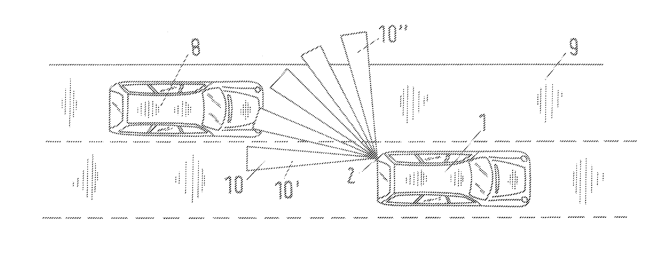
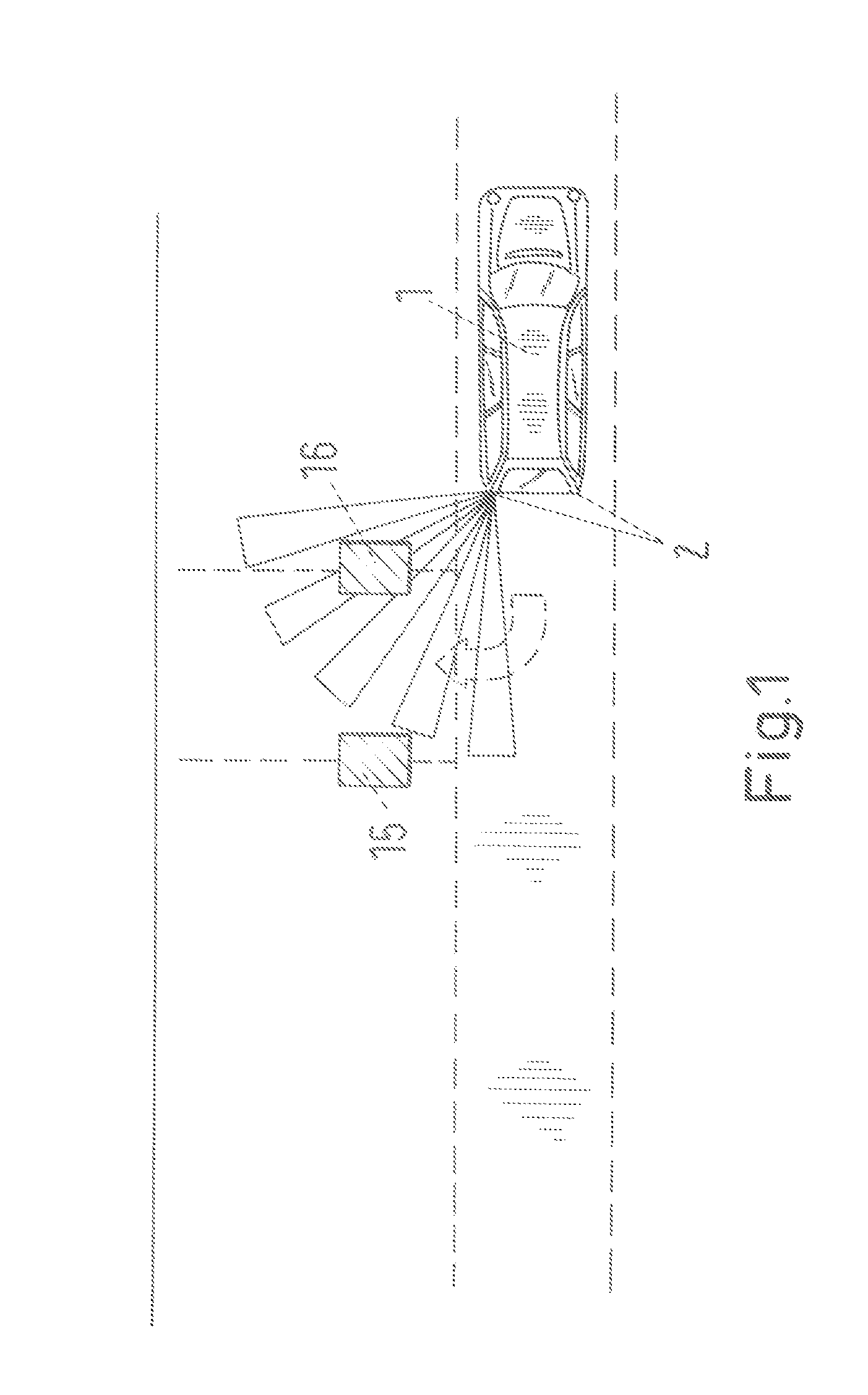
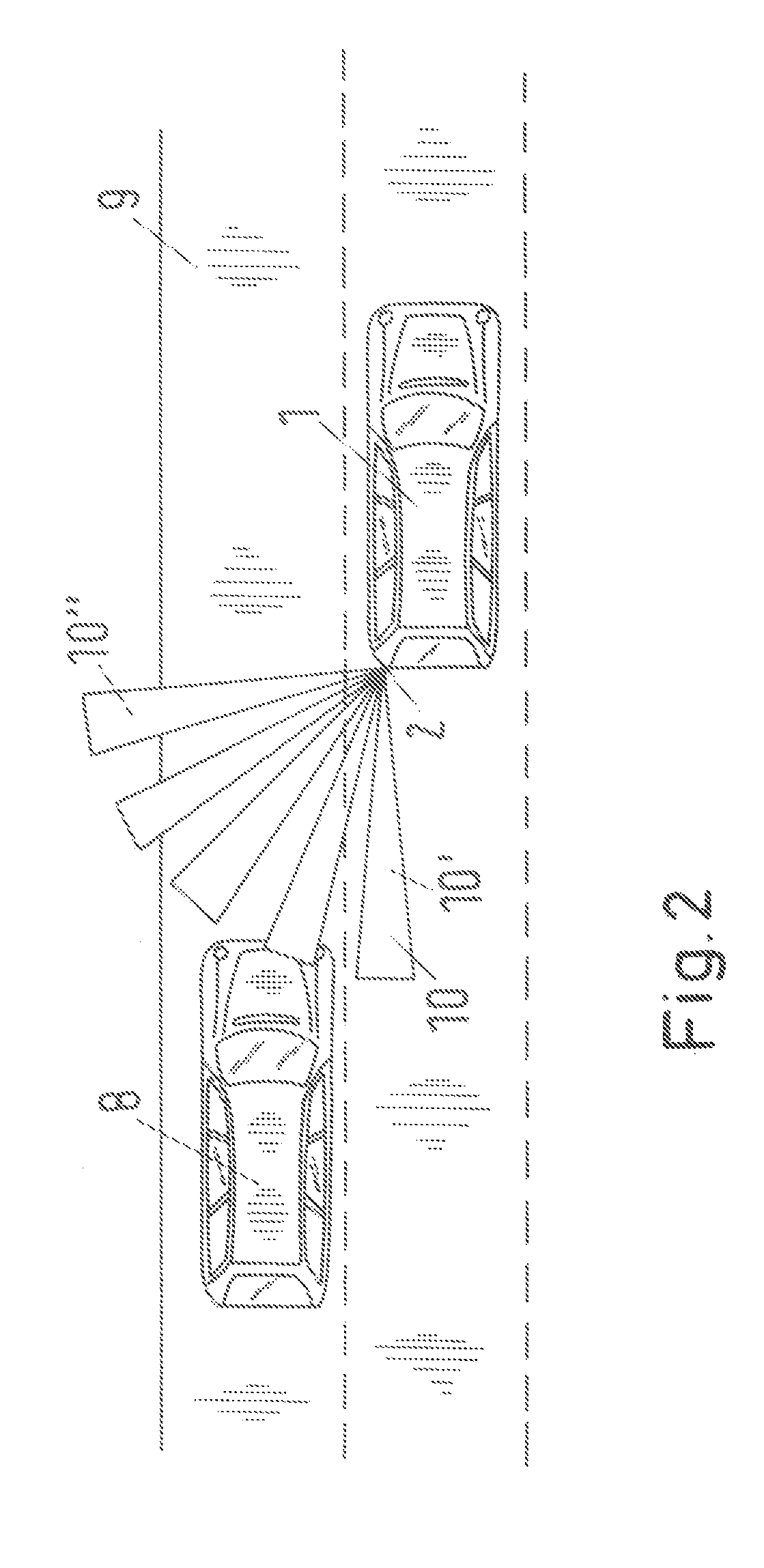
[0011]Referring to FIG. 1, a rear section of the motor vehicle 1 exhibits two tail light assembly 2, each of which exhibits at least one turn-signal light, a brake light and a rear light. In addition, the tail light assembly 2 may also exhibit a back-up light and / or a rear fog light. The tail light assembly 2 is designed in such a manner that they can be easily recognized by following road users irrespective of the viewing angle in relation to the tail, light assembly 2. The tail light, assembly 2 is designed in an advantageous manner so that they emit a constant brightness image in all directions.

[0012]FIG. 3 is a schematic drawing of the tail light assembly 2, which exhibits a turn-signal light 3, a rear light 4, a rear fog light 5, a back-up headlight 6 and a brake light 7. In the illustrated embodiment these signal lights 3 to 7 consist of LED's, which are distinguished by their long service life. However, the signal lights 3 to 7 may also be formed by other types of light sourc...


PUM


Abstract

A tail light assembly for a motor vehicle includes a plurality of signal lights to signal various operations. Each of the plurality of signal lights includes segments of lights that are independently operable. A sensor system is electrically connected to the segments of lights for measuring an event and for creating a control signal in response to the occurrence of an event. The tail light assembly also includes a control module electrically connected between the segments of lights and the sensor system. The control module receives the control signal and operates each of the plurality of segments of lights to ensure each of the plurality of signal lights can operate to maximize visibility through a plurality of positions with respect to the motor vehicle. Brightness of the signal lights is seen in varying degrees of brightness, depending on the angle at which the viewer sees the tail light

Description

BACKGROUND ART[0001]1. Field of the Invention[0002]The invention relates to a light, in particular a tail light assembly for a motor vehicle. More particularly, the invention relates to a tail light assembly of a motor vehicle that produces light from two different light sources.[0003]2. Description of the Related Art[0004]Tail light assemblies of motor vehicles have the problem that when the tail light assembly is turned on, the signal lights are seen as varying in brightness, depending on the angle at which the viewer sees the rear light. The result may be that in one case the rear light blinds the driver of a following motor vehicle, whereas the driver of a motor vehicle located on the side and behind the vehicle does not notice the rear light or rather the corresponding signal light at all or notices it too late. Therefore, the signal function of the light is curtailed.SUMMARY OF THE INVENTION[0005]A tail light assembly for a motor vehicle includes a plurality of signal lights t...

Claims


Application Information

Patent Timeline
Patent Type & Authority Applications(United States)
IPC IPC(8): B60Q1/00
CPCB60Q1/2607B60Q1/2603
Inventor STEFFEL, HANS-CLEMENSROSENSTEIN, FILIPMACK, BERND
Owner SCHEFENACKER VISION SYST GERMANY
Why Eureka
Try Eureka