
Optimal aircraft window shape for noise control

Active Publication Date: 2007-03-29
THE BOEING CO
View PDF12 Cites 7 Cited by
  • Summary
  • Abstract
  • Description
  • Claims
  • Application Information

AI Technical Summary

Benefits of technology

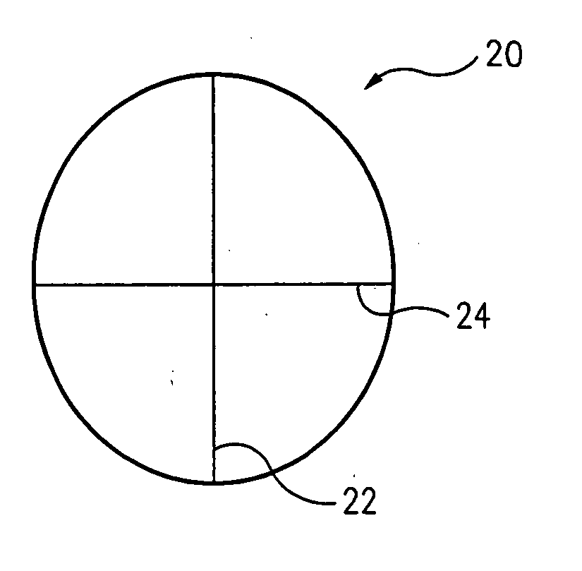
[0005] In accordance with the various exemplary embodiments thereof described herein, a shape for the windows of a subsonic passenger aircraft is provided that is optimized to maximize passenger visibility while minimizing the amount of acoustic noise transmitted through the windows to the interior of the aircraft during flight.
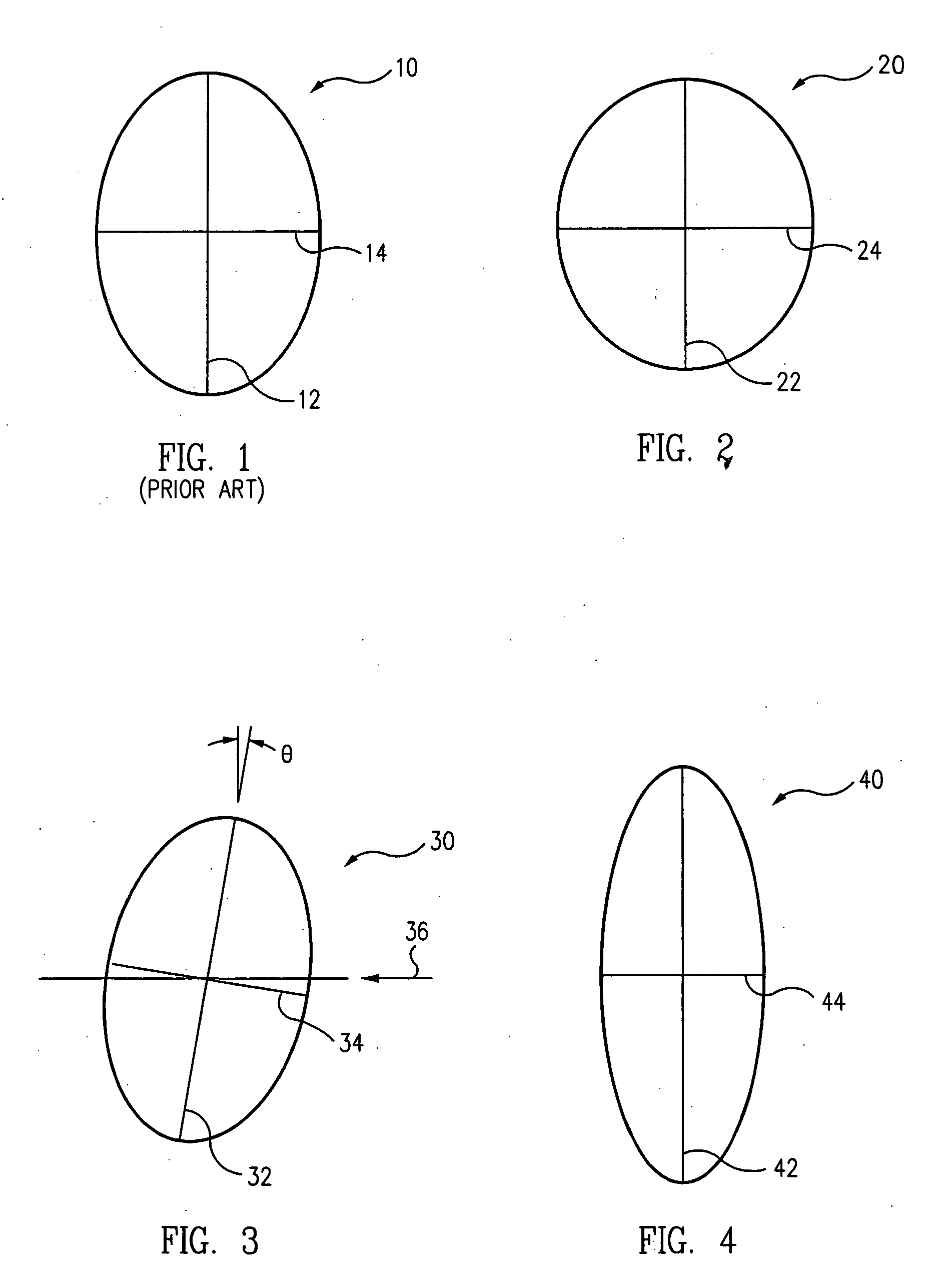
[0007] In another exemplary embodiment, the aircraft window can comprise a pair of substantially similar, elliptically shaped panes, e.g., an inboard pane and an outboard pane, each having a major axis about 20 inches long and a minor axis about 8 inches long, disposed in a parallel, spaced-apart relationship defining a space, or volume, therebetween. A correspondingly shaped bezel that circumscribes the inboard and outboard panes can be used to close the volume between the panes and sealingly couple the edges of the panes to the fuselage of the aircraft. In one advantageous alternative embodiment, the volume between the panes can be evacuated to lower the pressure in the volume to be substantially less than the ambient pressure surrounding the window.

Problems solved by technology

Both sources have large low-frequency components that are difficult to reduce without adding significant weight to the structure.
Besides weight limitations, the need to use optically transparent materials in the windows further complicates window noise control efforts.

Method used


Image

  • Optimal aircraft window shape for noise control
  • Optimal aircraft window shape for noise control
  • Optimal aircraft window shape for noise control

Examples


Embodiment Construction

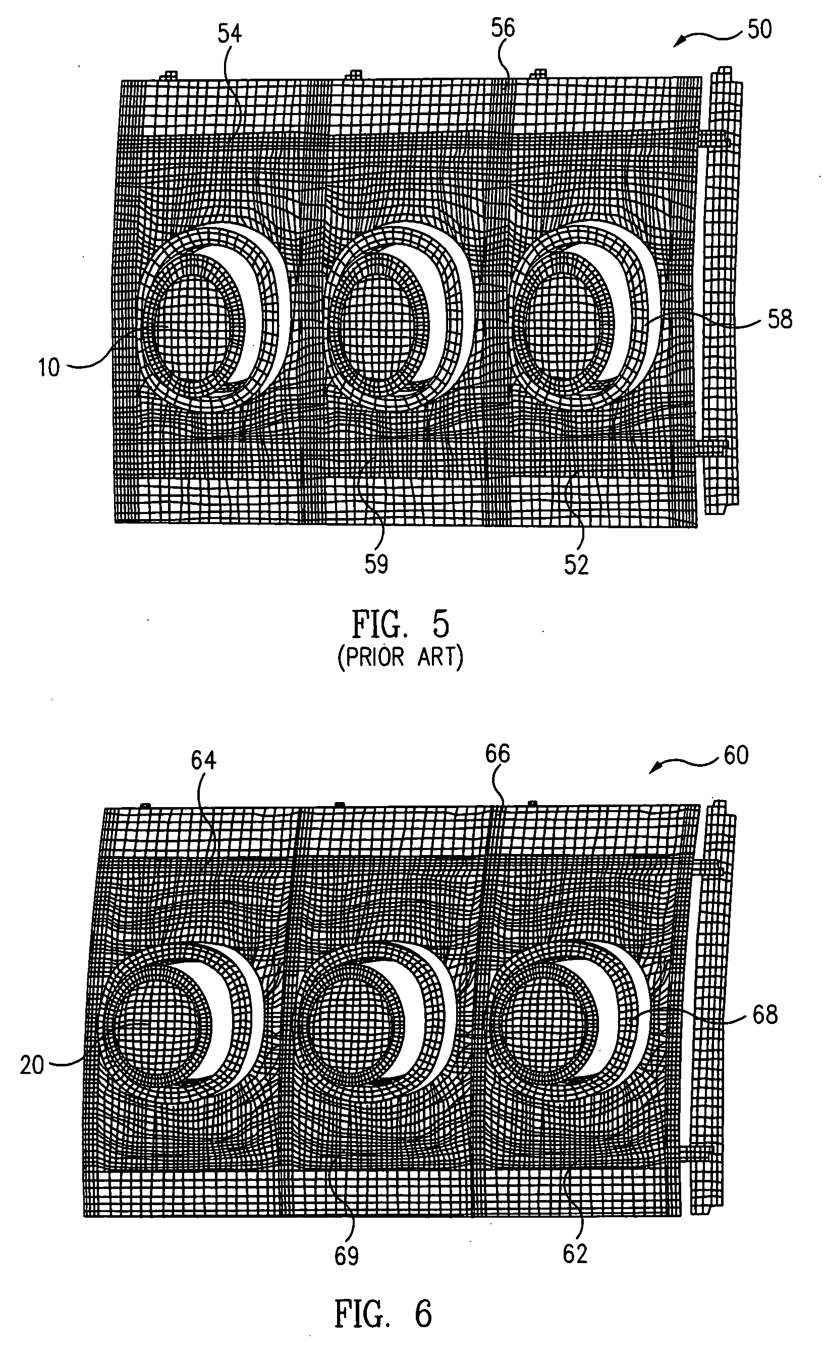
[0020] The technical problem addressed by this invention is the provision of a subsonic airliner passenger window shape that reduces the vibration levels of and the noise transmitted through a “window belt,” i.e., a section of the sidewalls of the aircraft's fuselage that includes the windows, that employs composite materials in its structure and a relatively large transparent window area. The problem evaluated involved the excitation of a section of the surface of the aircraft's fuselage including the above window belt by a turbulent boundary layer (“TBL”), and the results obtained were based on the structural response of the window belt to such an excitation.

[0021] The basic window shape selected for evaluation was that of an ellipse, because it was considered that such a window shape would best satisfy two competing design considerations, viz., a minimization or complete avoidance of any sharp corners or radii in the window that could act as stress raisers affecting the structur...


PUM


Abstract

A window for a subsonic passenger aircraft that provide maximum optical visibility while minimizing the amount of exterior acoustic noise transmitted through the windows to the passenger cabin during flight of the aircraft includes at least one substantially transparent window pane having the shape of an ellipse. The ellipse has a major axis and a minor axis, and the major axis is about twice as long as the minor axis and is disposed generally perpendicular to the direction of flight of the aircraft. In one exemplary embodiment, the window has a height of about 20 inches and a transparent area of about 141 square inches, and includes a pair of substantially similar window panes disposed in a parallel, spaced-apart relationship circumscribed by a mounting bezel. A plurality of the windows are each mounted with the bezels in spaced-apart rows in each of the opposite sidewalls of the aircraft fuselage.

Description

TECHNICAL FIELD [0001] This invention pertains to aircraft design in general, and in particular, to a shape for the windows of a subsonic passenger aircraft that is optimized to provide maximum passenger exterior visibility while minimizing the amount of acoustic noise transmitted through the windows to the interior of the aircraft during flight. BACKGROUND [0002] The current market for modem passenger aircraft intended for use in commercial aviation is highly competitive and necessitates that strict attention be paid to certain industry specific design requirements, such as passenger comfort. For example, the Boeing 787 passenger plane is being designed for “Best-In-Class” passenger comfort, and this includes cabin noise level goals that are as low or lower than any current large commercial aviation aircraft. [0003] In such aircraft, the airplane fuselage sidewalls in general, and the passenger windows in particular, are the dominant paths of external noise entry. This is of primar...

Claims


Application Information

Patent Timeline
IPC IPC(8): B64C1/14
CPCB64C1/1484B64C1/1492
Inventor RASSAIAN, MOSTAFALEE, JUNG-CHUANMONTGOMERY, JOSHGUARD, PETER S.STADUM, MARK A.MIKULENCAK, PAUL E.BRIGMAN, RICHARD W.
Owner THE BOEING CO
Learn More