Method and apparatus for embedded battery cells and thermal management

a battery cell and thermal management technology, applied in secondary cell servicing/maintenance, cell components, instruments, etc., can solve the problems of cooling system louder, entire portable computer to get hotter and hotter to the touch, and degradation of main battery, so as to minimize the amount and size of dedicated heat sinks, the effect of high thermal conductivity and reducing heat transfer

Inactive Publication Date: 2010-05-06
BOSTON POWER INC
View PDF99 Cites 26 Cited by
  • Summary
  • Abstract
  • Description
  • Claims
  • Application Information

AI Technical Summary

Benefits of technology

[0012]Current notebook personal computers (or notebook PC) typically include an external battery that is enclosed in a plastic case and designs attempt to minimize heat transfer from the notebook to the battery pack because heat is known to degrade battery cells in their present form. Embodiments of the present invention may allow for battery cells to be embedded into the notebook PC design and for the embedded battery cells to act as a heat sinks if a means exists for transporting the heat out of the notebook PC. The battery cells may be adjacent to surfaces made out of material having high thermal conductivity, e.g., metal, engineered thermal materials, or the like. Using the embedded battery cells may minimize the amount and size of dedicated heat sinks, heat pipes, fans and other means of thermal management inside the notebook PC. The reduction of the need for both passive and active thermal management inside the notebook PC saves cost, space, and allows the manufacturer of the notebook PC to have more freedom in the overall designing process.

Problems solved by technology

Degradation of the main battery may be due to use or due to failures in the cooling systems of the portable computer.
Failures in the cooling system (e.g., a fan or heatsink) may be caused by collection of dust and debris, which will cause the entire portable computer to get hotter and hotter to the touch and for the cooling system to become louder over time.

Method used


Image

  • Method and apparatus for embedded battery cells and thermal management
  • Method and apparatus for embedded battery cells and thermal management
  • Method and apparatus for embedded battery cells and thermal management

Examples


Embodiment Construction

[0020]The foregoing will be apparent from the following more particular description of example embodiments of the invention, as illustrated in the accompanying drawings in which like reference characters refer to the same parts throughout the different views. The drawings are not necessarily to scale, emphasis instead being placed upon illustrating embodiments of the present invention.

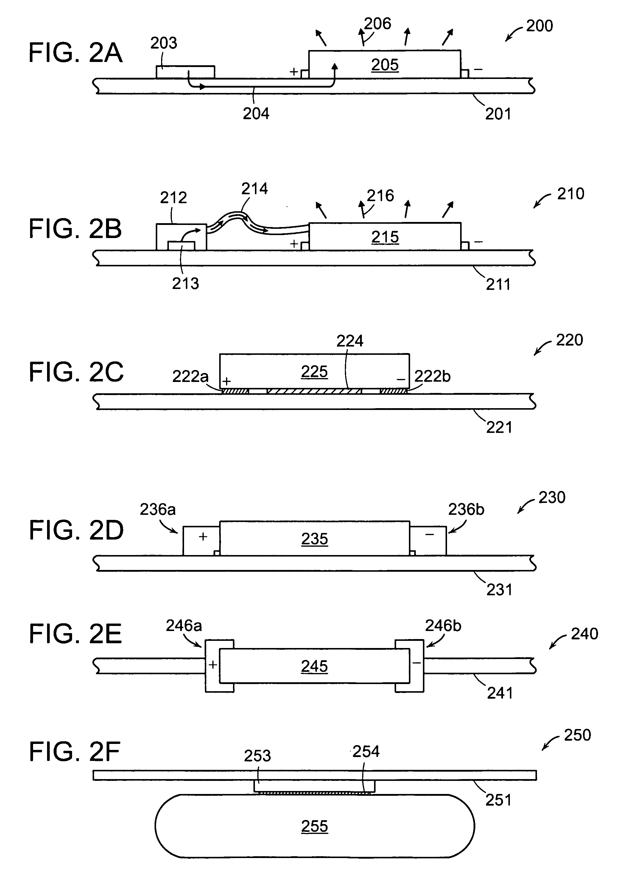
[0021]The present application is directed to a device comprising: at least one heat generating component and a battery cell thermally coupled to the at least one heat generating component. The device may be portable. The battery cell may be rechargeable, which includes lithium in a cathode of the battery.

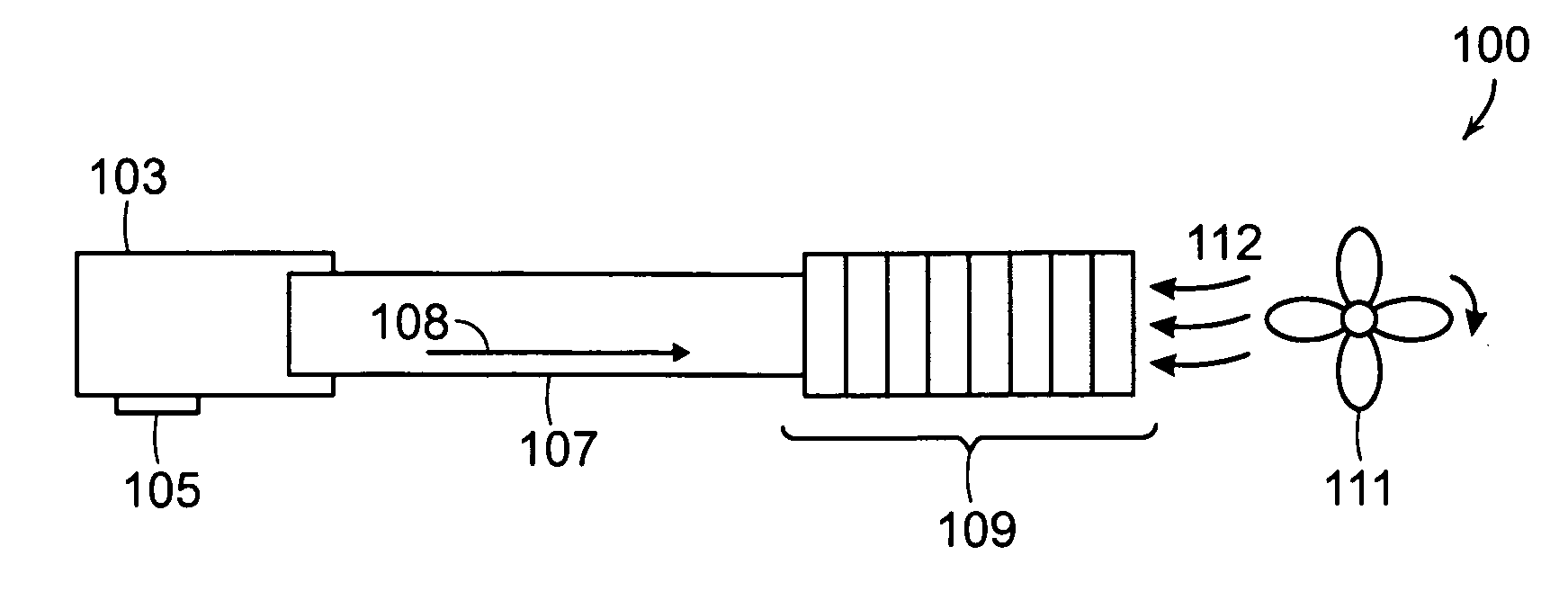
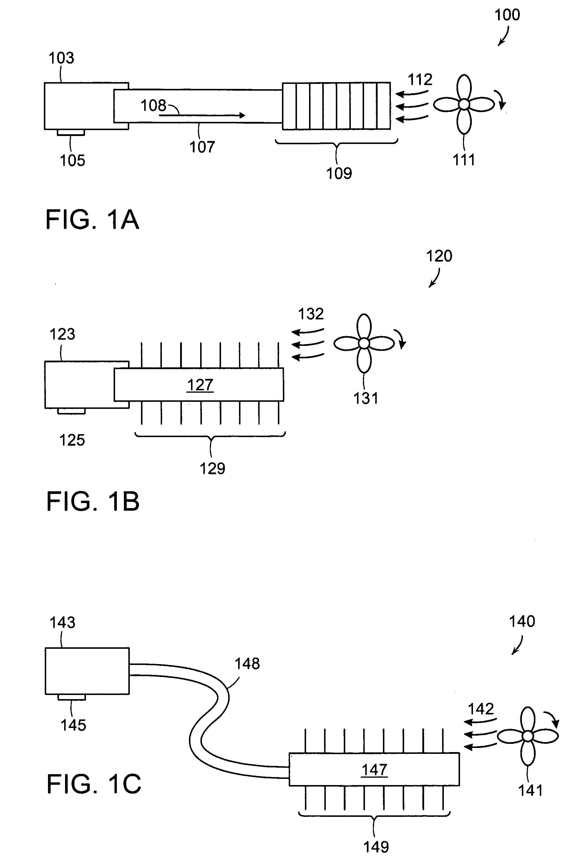
[0022]Several configurations of the present invention for thermal management of a device using a battery are illustrated in FIGS. 1A-1C. Each configuration involves using a battery as a thermal heat transfer channel (e.g., heat transfer 108 of FIG. 1A) from CPU / GPU chip to extruded features (e.g., radi...


PUM

PropertyMeasurementUnit
temperatureaaaaaaaaaa
weightaaaaaaaaaa

Abstract

Battery cells are embedded in a device to control thermal management of the device. One embodiment includes an embedded battery arrangement that improves thermal management of a portable computer, such as heat transfer and dissipation from heat generating components of the portable computer (including, for example, central processing unit chips or graphics processing unit chips). In one specific embodiment, a printed circuit board is mounted to a battery pack to cause improved radiation of heat from heat generating components of the portable computer to outside of the portable computer housing. In another embodiment, battery cells are distributed within the housing of a portable computer that improves thermal management.

Description

RELATED APPLICATIONS[0001]This application claims the benefit of U.S. Provisional Application No. 61 / 191,846, filed on Sep. 12, 2008, and U.S. Provisional Application No. 61 / 194,382, filed on Sep. 26, 2008 for Embedded Battery Cells and Thermal Management of Personal Computers by Per Onnerud, Phillip E. Partin, Scott Milne, Yanning Song, Richard V. Chamberlain, II, and Nick Cataldo, the teachings of both of which are incorporated herein by reference in their entirety.BACKGROUND OF THE INVENTION[0002]Portable computers (or notebooks) typically include a single main battery that is charged and stores energy from an external alternating current to a direct current (AC / DC) adapter. Currently the main battery is a lithium ion battery and adds approximately one pound to the overall weight of the portable computer. The main battery degrades and may need to be replaced in one to five years. Degradation of the main battery may be due to use or due to failures in the cooling systems of the po...

Claims


Application Information

Patent Timeline
Patent Type & Authority Applications(United States)
IPC IPC(8): F28F7/00H01M10/50H01M50/119H01M50/209H01M50/244H01M50/247
CPCG06F1/203G06F1/206G06F1/3203H01M2/0275H01M2/1022H01M2/1061H01M2/1094H01M10/0525H01M10/44H01M10/441H05K1/0203H05K2201/10037H05K2201/10537H05K2201/10689H01M10/6563H01M10/6551H01M10/6552H01M10/667H01M10/623H01M10/613Y02E60/10H01M50/209H01M50/24H01M10/658H01M50/247H01M50/244H01M50/119
Inventor ONNERUD, PERPARTIN, PHILLIP E.MILNE, SCOTTSONG, YANNINGCHAMBERLAIN, II, RICHARD V.CATALDO, NICK
Owner BOSTON POWER INC
Why Eureka
Try Eureka