
Solid-oxide fuel cell assembly having a thermal enclosure within a structural enclosure

a fuel cell and thermal enclosure technology, applied in the direction of fuel cell details, propulsion parts, final product manufacturing, etc., can solve the problems of complex and costly fabrication and assembly, and achieve the effect of minimizing heat transfer

Inactive Publication Date: 2005-09-13
APTIV TECH LTD
View PDF18 Cites 19 Cited by
  • Summary
  • Abstract
  • Description
  • Claims
  • Application Information

AI Technical Summary

Benefits of technology

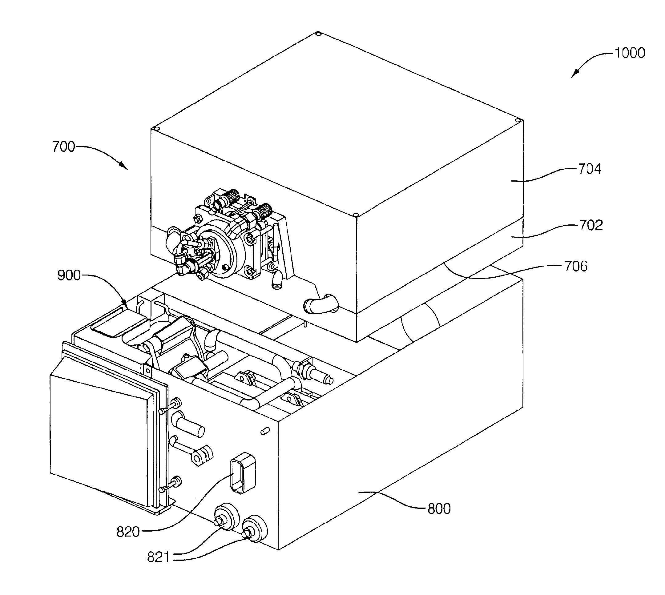
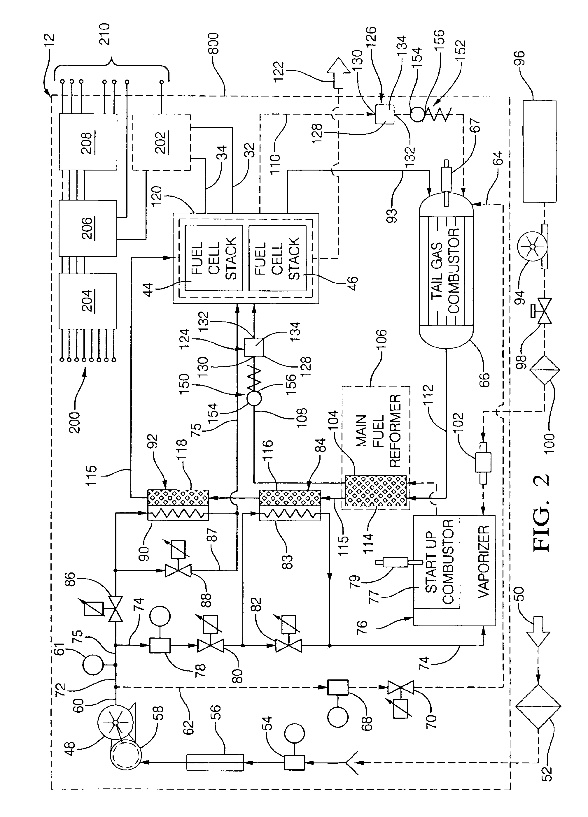
[0009]Briefly described, in a solid-oxide fuel cell system, the “hot” components, e.g., the fuel cell stacks, the fuel reformer, tail gas combuster, heat exchangers, and fuel / air manifold, are contained in a “hot zone” within a thermal enclosure. The thermal enclosure is intended specifically for minimizing heat transfer to its exterior and has no significant structural or protective function for its contents. A two-part clamshell arrangement allows all piping and leads which must pass through the enclosure to do so at the join line between the parts, thus eliminating need for ports and fittings in the thermal enclosure. A separate and larger structural enclosure surrounds the thermal enclosure, defining a “cool zone” outside the thermal enclosure for incorporation of “cool” components, e.g., the air supply system and the electronic control system.

Problems solved by technology

Prior art fuel cell systems utilize a single enclosure to provide all functions, which can be complex and costly to fabricate and assemble, and consumptive of space.

Method used


Image

  • Solid-oxide fuel cell assembly having a thermal enclosure within a structural enclosure
  • Solid-oxide fuel cell assembly having a thermal enclosure within a structural enclosure
  • Solid-oxide fuel cell assembly having a thermal enclosure within a structural enclosure

Examples


Embodiment Construction

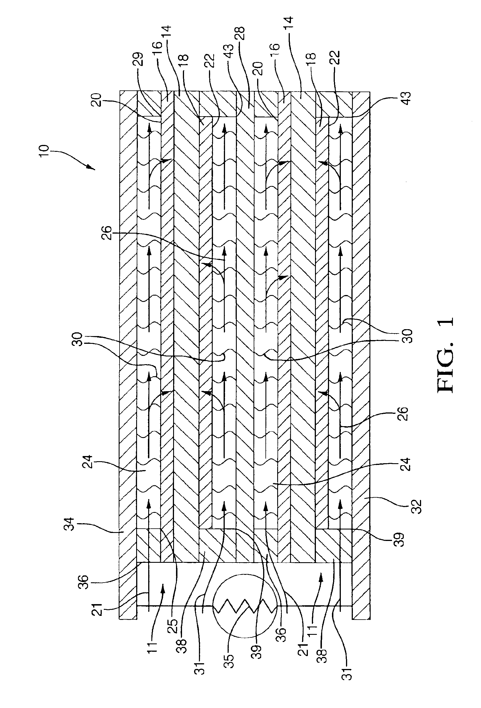
[0028]Referring to FIG. 1, a fuel cell stack 10 includes elements known in the art of solid-oxide fuel cell stacks comprising more than one fuel cell. The example shown includes two identical fuel cells 11, connected in series, and is of a class of such fuel cells said to be “anode-supported” in that the anode is a structural element having the electrolyte and cathode deposited upon it. Element thicknesses as shown are not to scale.

[0029]Each fuel cell 11 includes an electrolyte element 14 separating an anodic element 16 and a cathodic element 18. Each anode and cathode is in direct chemical contact with its respective surface of the electrolyte, and each anode and cathode has a respective free surface 20,22 forming one wall of a respective passageway 24,26 for flow of gas across the surface. Anode 16 of one fuel cell 11 faces and is electrically connected to an interconnect 28 by filaments 30 extending across but not blocking passageway 24. Similarly, cathode 18 of fuel cell 11 fac...


PUM

PropertyMeasurementUnit
voltageaaaaaaaaaa
voltageaaaaaaaaaa
elevated temperatureaaaaaaaaaa

Abstract

A solid-oxide fuel cell system having “hot” components, e.g., the fuel cell stacks, the fuel reformer, tail gas combuster, heat exchangers, and fuel / air manifold, contained in a “hot zone” within a thermal enclosure intended specifically for minimizing heat transfer to its exterior and having no significant structural or protective function for its contents. A two-part clamshell arrangement allows all piping and leads which must pass through the enclosure to do so at the join line between the parts, thus eliminating need for ports and fittings in the thermal enclosure. A separate and larger structural enclosure surrounds the thermal enclosure, defining a “cool zone” outside the thermal enclosure for incorporation of “cool” components, e.g., the air supply system and the electronic control system, and providing structural protection for all components of the fuel cell system.

Description

TECHNICAL FIELD[0001]The present invention relates to hydrogen / oxygen fuel cells having a solid-oxide electrolytic layer separating an anode layer from a cathode layer; more particularly, to fuel cell assemblies and systems comprising a plurality of individual fuel cells in a stack wherein air and reformed fuel are supplied to the stack; and most particularly, to a fuel cell system wherein core components which operate at very high temperatures in a hot zone are contained in a thermal enclosure disposed within a separate and larger structural enclosure which also houses cool zone components.BACKGROUND OF THE INVENTION[0002]Fuel cells which generate electric current by the electrochemical combination of hydrogen and oxygen are well known. In one form of such a fuel cell, an anodic layer and a cathodic layer are separated by an electrolyte formed of a ceramic solid oxide. Such a fuel cell is known in the art as a “solid oxide fuel cell” (SOFC). Hydrogen, either pure or reformed from h...

Claims


Application Information

Patent Timeline
Patent Type & Authority Patents(United States)
IPC IPC(8): B60L11/18B60K1/04H01M2/02H01M8/02H01M8/12H01M8/10H01M8/04H01M8/06B01J19/24C01B3/38H01M8/24
CPCB01J19/249C01B3/386H01M8/04014H01M8/04201H01M8/04395H01M8/04753H01M8/04768H01M8/04776H01M8/0618H01M8/1246H01M8/2465H01M8/2475H01M8/249B01J2219/2453B01J2219/2477B01J2219/2496C01B2203/0261C01B2203/066C01B2203/0883C01B2203/1288H01M8/0662H01M8/2425H01M2250/20Y02E60/521Y02E60/525Y02T90/32Y02E60/50Y02P70/50Y02T90/40H01M8/2432H01M8/2484
Inventor HALTINER, JR., KARL J.FAVILLE, MICHAEL T.KELLY, SEAN M.
Owner APTIV TECH LTD
Learn More