Die assembly and production process for profile extrusion

a technology of thermoplastic resin and composite profiles, applied in the field of improved, can solve the problems of difficult to meet the requirements of outdoor applications, and limited use of profiles, so as to prevent the occurrence of melt fractures and minimize the effect of us

Inactive Publication Date: 2008-01-15
CARNEY TIMBER CO INC PLAINTIFF
View PDF19 Cites 19 Cited by
  • Summary
  • Abstract
  • Description
  • Claims
  • Application Information

AI Technical Summary

Benefits of technology

[0013]The present invention overcomes the disadvantages in the prior art by providing an improved die assembly for the extrusion of thermoplastic resin cellulosic fiber composite profiles meant to minimize and substantially prevent the occurrence of melt fracture on the surface of the extruded profiles.
[0014]The die assembly of the present invention is designed for the continuous production of a thermoplastic resin and cellulosic fiber composite profile having a desired cross-section and an exterior surface, wherein the die assembly has an axis oriented from an upstream end to a downstream end. Comprising the die assembly are: a flow passage through the die assembly that results in a generally balanced flow of the thermoplastic resin and cellulosic fiber composite compound from an upstream inlet to a downstream outlet that are displaced along the axis of the die assembly; a heated compression zone that has an inlet which corresponds to the die assembly inlet and an outlet which corresponds to at least a portion of the upstream end of the flow passage through the die assembly; a heated transition zone that has an inlet and an outlet, wherein the inlet of the transition zone corresponds to the outlet of the compression zone; a heated converging die zone that has an inlet and an outlet, wherein the inlet of the die zone corresponds to the outlet of the transition zone and the outlet of the die zone generally corresponds to the cross-section of the desired composite profile; a die land with an inlet and an outlet, wherein the die land corresponds to at least a portion of the downstream end of the flow passage through the die assembly, the inlet of the die land corresponds to the outlet of the die zone, the outlet of the die land corresponds to the outlet of the die assembly and the cross-section of die land at the outlet corresponds to the cross-section of the desired composite profile; a cooling means to maintain the temperature of the die land below the melting point temperature of the thermoplastic resin in order to minimize and substantially prevent the occurrence of melt fracture on the exterior surface of the composite profile; and a thermal break between the die zone and the die land meant to minimize heat transfer between the die zone and the die land.
[0015]The die assembly of the present invention can also be adapted for the extrusion of hollow thermoplastic resin cellulosic fiber composite profiles without the occurrence of melt fracture. The die assembly for the production of hollow composite profiles, which have at least one longitudinal hollow channel and an interior surface, further comprises a mandrel meant to form the longitudinal hollow channels in the composite profile, wherein: the mandrel, which has an upstream portion and a downstream portion, is positioned within the flow passage through the die assembly and forms an annular flow passage that has upstream and downstream ends and is oriented along the axis of the die assembly; the mandrel is held in position by at least one mandrel support and the mandrel supports are generally perpendicular to the mandrel and to the axis of the die assembly, intersect the annular flow passage and are rigidly connected to the upstream portion of the mandrel; the downstream portion of the mandrel is comprised of at least one core and is positioned within the die land; the number of cores corresponds to the number of hollow channels in the composite profile and the cross-section of the cores generally corresponds to the cross-section of hollow channels in the composite profile; and the cores are equipped with cooling means to maintain the temperature of the cores below the melting point temperature of the thermoplastic resin in order to minimize and substantially prevent the occurrence of melt fracture on the interior surface of the composite profile.

Problems solved by technology

While these products have been used successfully in a large number of applications as substitutes for solid wood, their use has been typically limited to applications which do not expose them to moisture, since they can deteriorate very quickly in wet or even highly humid environments.
As such, they have seen very limited use in outdoor applications.
However, due to the typically high cellulose fiber content (40 to 80 weight percent), the extrusion of composite profiles presents challenges which are not typical of other extrusion processes.
The most significant issue in extruding composite profiles is the occurrence of melt fracture.
In a paper titled “Profile Extrusion of Highly Filled Recycled HDPE” Suwanda, et al. describes melt fracture as a large scale deformation of the surface of the extrudate as it leaves the die resulting in tears in the extrudate and an unacceptably rough surface finish.
In U.S. Pat. No. 5,725,939, Nishibori observed that in a conventional sheet die, the large frictional resistance of the inner surfaces of the die causes the composite material being extruded not to flow smoothly causing the extrudate to be non-uniform and for cavities to form in the extrudate.
While the above approaches to reducing the occurrence of melt fracture during the extrusion of composite profiles have been used with varying degrees of success to produce composite profiles with improved surface finishes, these approaches also have their drawbacks.
Increasing the temperature of the die or the surface of the extrudate as is taught by Goforth, et al. and Brooks, et al. can result in degradation or burning of the cellulosic fibers if the die temperature is sufficiently high, thereby creating a burned appearance on the surface of the composite profile.
Using a low friction land section to reduce the drag on the surface of the profile in the land section in combination with a passage connected to the land which contains a cooling medium as is taught by Muller, et al. is not easily adapted for the production of hollow articles.
In addition, the abrasive nature of thermoplastic resin cellulosic fiber composite could cause substantial wear of the low friction land thereby changing the cross-section of the extruded profile with increasing wear.
Using a cooled shaper to solidify the surface of the profile in order to prevent melt fracture as is taught by Suwanda has a substantial disadvantage, particularly with hollow profiles, in that once the surface of the profile is solidified, the ability to use the various methods known in the art to calibrate or maintain the desired cross-section of the extruded profile during cooling can be significantly limited.
Nishibori's use of a die with inner walls that are covered or coated with a layer of material, such as a fluoro resin, that has an extremely small coefficient of friction has a disadvantage similar to Muller, et al. in that the abrasive nature of composite material could cause substantial wear of the low friction die wall material, thereby changing the cross-section of the extruded profile over time.
This results in composite profiles which can easily crack between the strands when fasteners such as nails or screws are driven through the profile.

Method used


Image

  • Die assembly and production process for profile extrusion
  • Die assembly and production process for profile extrusion
  • Die assembly and production process for profile extrusion

Examples


Embodiment Construction

[0028]Although the invention will be described in terms of specific embodiments, it will be readily apparent to those skilled in the art that various modifications, rearrangements and substitutions can be made without parting from the spirit of this invention.

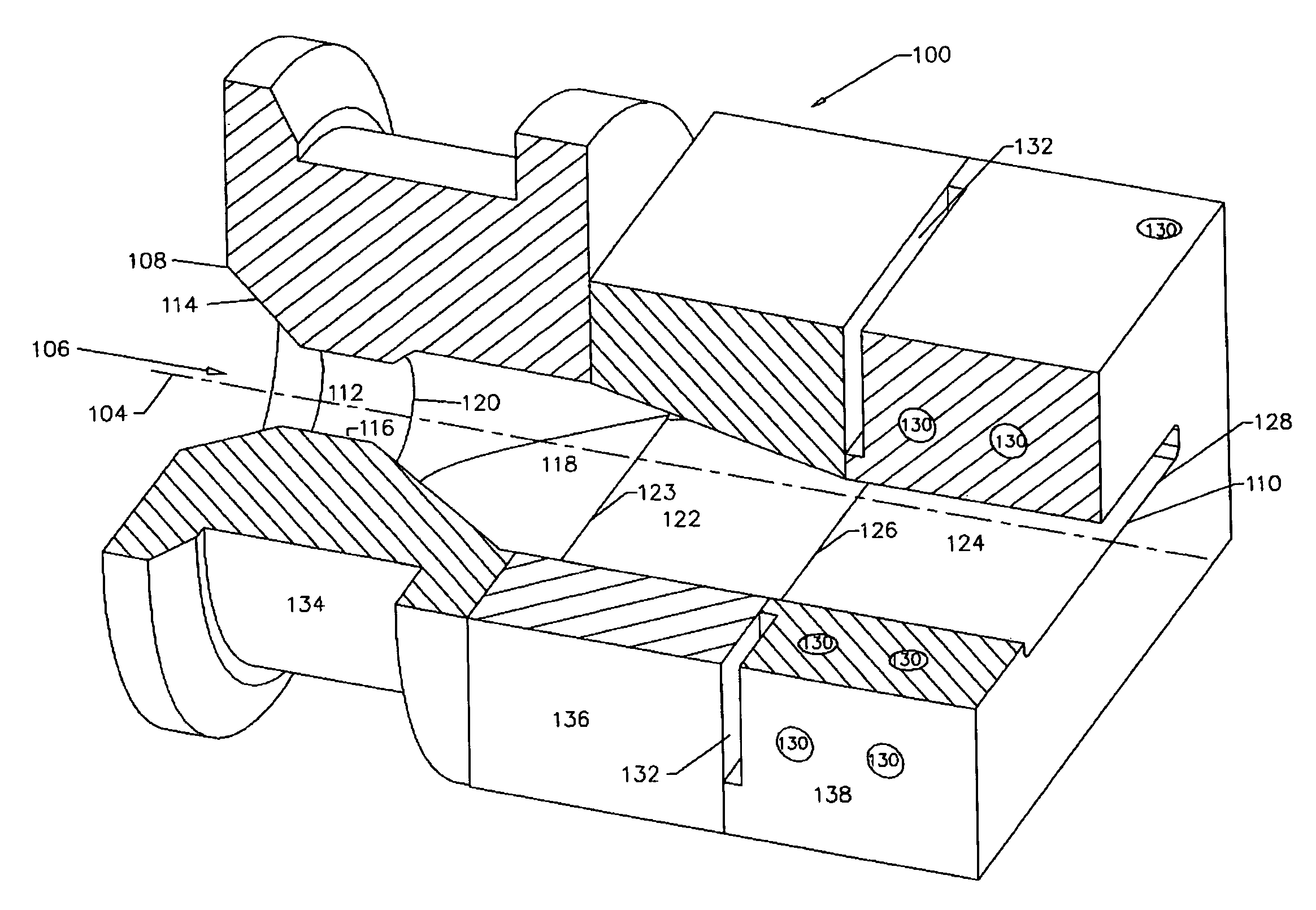
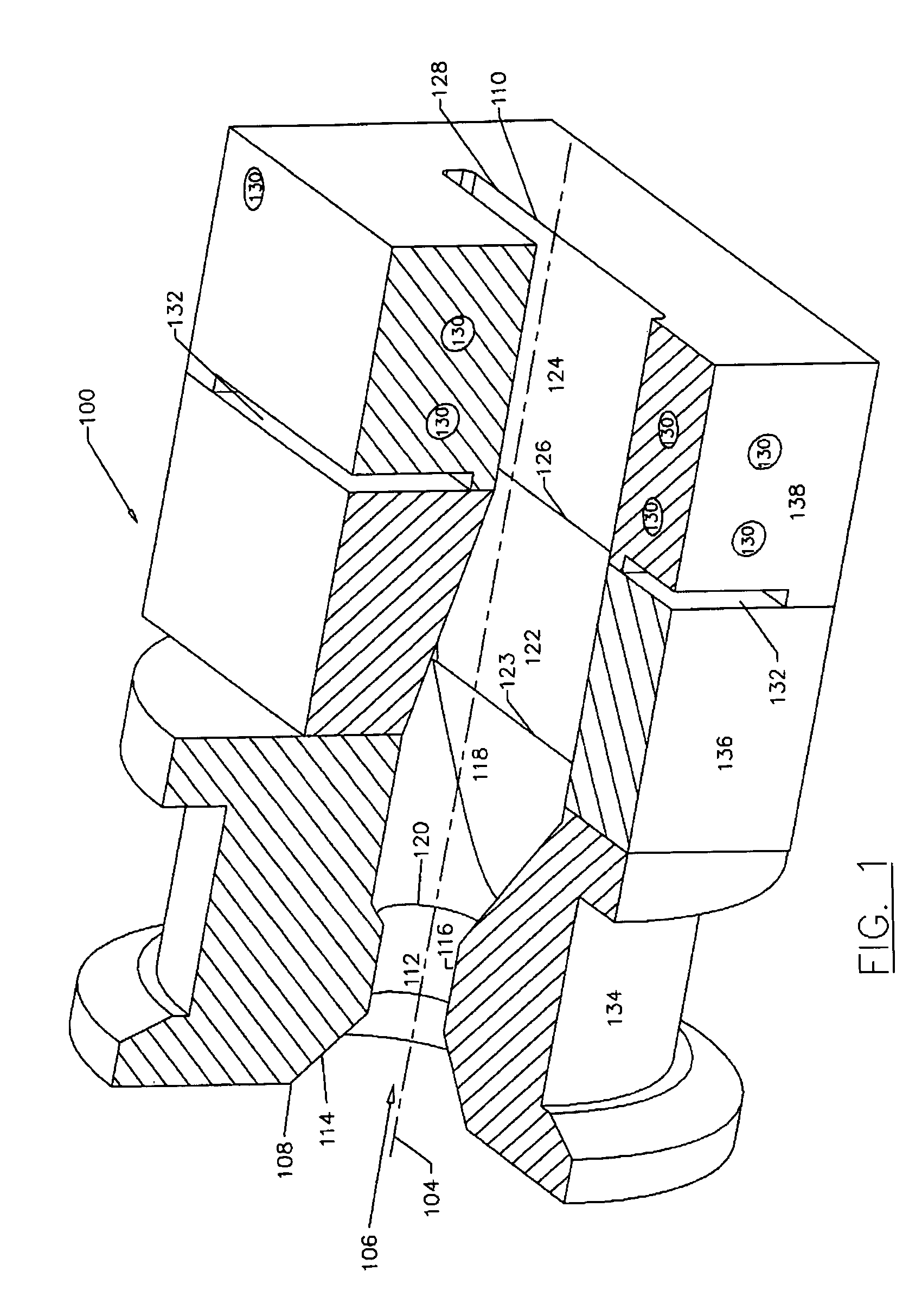
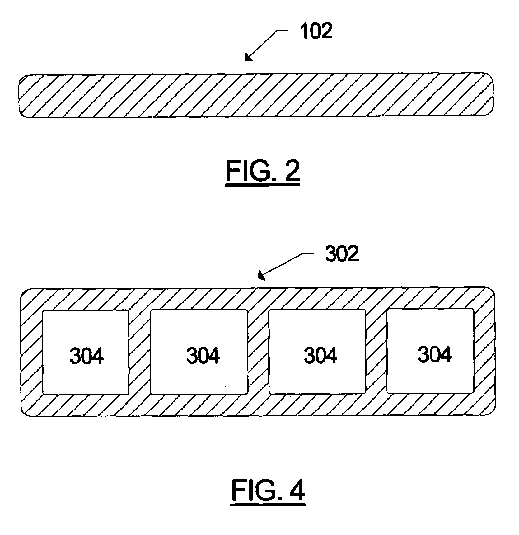
[0029]FIG. 1 shows a sectional view of one embodiment of a die assembly 100 of the present invention for the continuous production of a solid thermoplastic resin cellulosic fiber composite profile having a rectangular cross-section, while FIG. 2 shows a cross-sectional view of the solid profile 102 produced with the die assembly 100 shown in FIG. 1. The die assembly 100 has an axis 104 oriented from its upstream end to its downstream end. Located within the die assembly 100 is a balanced flow passage 106 through which composite compound is extruded from an upstream inlet 108 to a downstream outlet 110. The inlet 108 and outlet 110 are located in the upstream and downstream ends of the die assembly, respectively. The first part ...


PUM

PropertyMeasurementUnit
softening pointaaaaaaaaaa
temperatureaaaaaaaaaa
melting point temperatureaaaaaaaaaa

Abstract

The invention discloses an improved die assembly for the extrusion of thermoplastic resin cellulosic fiber composite profiles meant to minimize and substantially prevent the occurrence of melt fracture on the surface of the extruded composite profiles. Comprising the die assembly are a balanced flow passage having a heated compression zone, a heated transition zone, a heated converging die zone, a die land, which corresponds to at least a portion of the downstream end of the flow passage and is cooled to temperature below the melting point temperature of the thermoplastic resin. The invention also discloses a production process for composite profiles which includes the steps of providing resin and fiber, producing a composite compound, processing the compound through an extrusion system, extruding the compound through the die assembly to form the desired profile, cooling the profile and cutting it to length. Also disclosed are products produced by the production process.

Description

FIELD OF THE INVENTION[0001]This invention is directed to an improved die assembly and production process for the extrusion of thermoplastic resin cellulosic fiber composite profiles which are meant to minimize and substantially prevent the occurrence of melt fracture on the surface during extrusion of the composite profiles and composite profiles produced by said production process.BACKGROUND TO THE INVENTION[0002]Cellulosic fiber composites, which are used as wood substitute materials, have been available for many years. These composites, which include particle board, medium density fiber board (MDF), oriented strand board (OSB) and laminated veneer lumber(LVL) among others, typically consist of wood particles of various sizes (depending on the product being produced) which are bound together with a relatively small fraction (5% to 15% on a weight basis) of thermosetting resin such as urea-formaldehyde or methy-diphenyl-isocyanate (MDI). In addition to wood particles, these produc...

Claims


Application Information

Patent Timeline
Patent Type & Authority Patents(United States)
IPC IPC(8): B29C47/12B29C47/90B29C48/07B29C48/09B29C48/11B29C48/12B29C48/29B29C48/30B29C48/86B29C48/87B29C48/90
CPCB29C47/0019B29C47/86B29C47/864B29C47/1018Y10T428/1372B29C47/1045B29C47/1063B29C47/882B29C47/901B29C2793/009B29K2001/00B29K2023/06B29K2023/12B29K2025/00B29K2027/06B29K2105/0005B29K2105/0026B29K2105/0032B29K2105/0044B29K2105/005B29K2105/06B29K2105/26B29K2105/12Y10T428/1348B29C48/865B29C48/29B29C48/07B29C48/09B29C48/11B29C48/12B29C48/287B29C48/2886B29C48/86B29C48/87B29C48/9115B29C48/916B29C48/919B29C48/90B29C48/901B29C48/905B29C48/908Y10T428/3188
Inventor PABEDINSKAS, ARUNAS ANTANAS
Owner CARNEY TIMBER CO INC PLAINTIFF
Why Eureka
Try Eureka