Adiabatic plug flow reactors and processes incorporating the same

a plug flow reactor and reactor technology, applied in chemical/physical/physical-chemical processes, halogenated hydrocarbon preparations, organic chemistry, etc., can solve the problems of additional difficulties in temperature control and heat transfer characteristics, reduce the quality of plug flow, and achieve optimized mixing , the effect of facilitating the reduction of backmixing and/or recirculation

Inactive Publication Date: 2016-12-01
BLUE CUBE IP
View PDF3 Cites 21 Cited by
  • Summary
  • Abstract
  • Description
  • Claims
  • Application Information

AI Technical Summary

Benefits of technology

[0006]Such a reactor is provided herein. More specifically, the reactor described herein can provide one or more of more accurate temperature control, minimization of heat transfer into and / or out of the reactor, appropriate residence times of reaction components and or optimized mixing. As a result, desired conversions and / or selectivities can be seen. The reactor is thus particularly well suited for reactions comprising thermally sensitive components such as catalysts that may otherwise exhibit reduced lifetimes, or reaction components that undesirably react or decompose at temperatures within the processing specifications of the process desirably carried out within the reactor.
[0007]In one aspect of the present invention, an adiabatic plug flow reactor suitable for use in a continuous, gas phase, free radical process for the production of chlorinated and / or fluorinated propene and higher alkenes is provided, wherein the reactor comprises a design that facilitates reduced backmixing and / or recirculation prior to entry into, or upon exit from, the reactor, or reduced formation of by-products during any backmixing that may occur. In some embodiments, the reactor may further comprise a design that minimizes the production of by-products at a desired conversion.
[0008]Several such designs are provided, including i) a design that minimizes heat transfer to and / or from the reactor; ii) a design that optimizes the flow of the reaction components at the boundary between the reaction components and at least a portion of at least one reactor tube wall; iii) a design that facilitates a reduction of the temperature of a reactor effluent to a temperature below which substantial formation of by-products does not occur, and / or iv) a design that allows the production rate of a process conducted in the reactor to be adjusted by controlling the temperature of the reactor effluent. Combinations of one or more of these may be utilized, in which case the benefits provided by one may be further leveraged, perhaps even synergistically, by addition of the other(s).

Problems solved by technology

For example, substantial mixing in the axial direction can reduce the quality of plug flow, as can wall friction and diffusion, etc.
Reactors of such length can then present additional difficulties in temperature control and heat transfer characteristics.

Method used


Image

  • Adiabatic plug flow reactors and processes incorporating the same
  • Adiabatic plug flow reactors and processes incorporating the same
  • Adiabatic plug flow reactors and processes incorporating the same

Examples


example 2

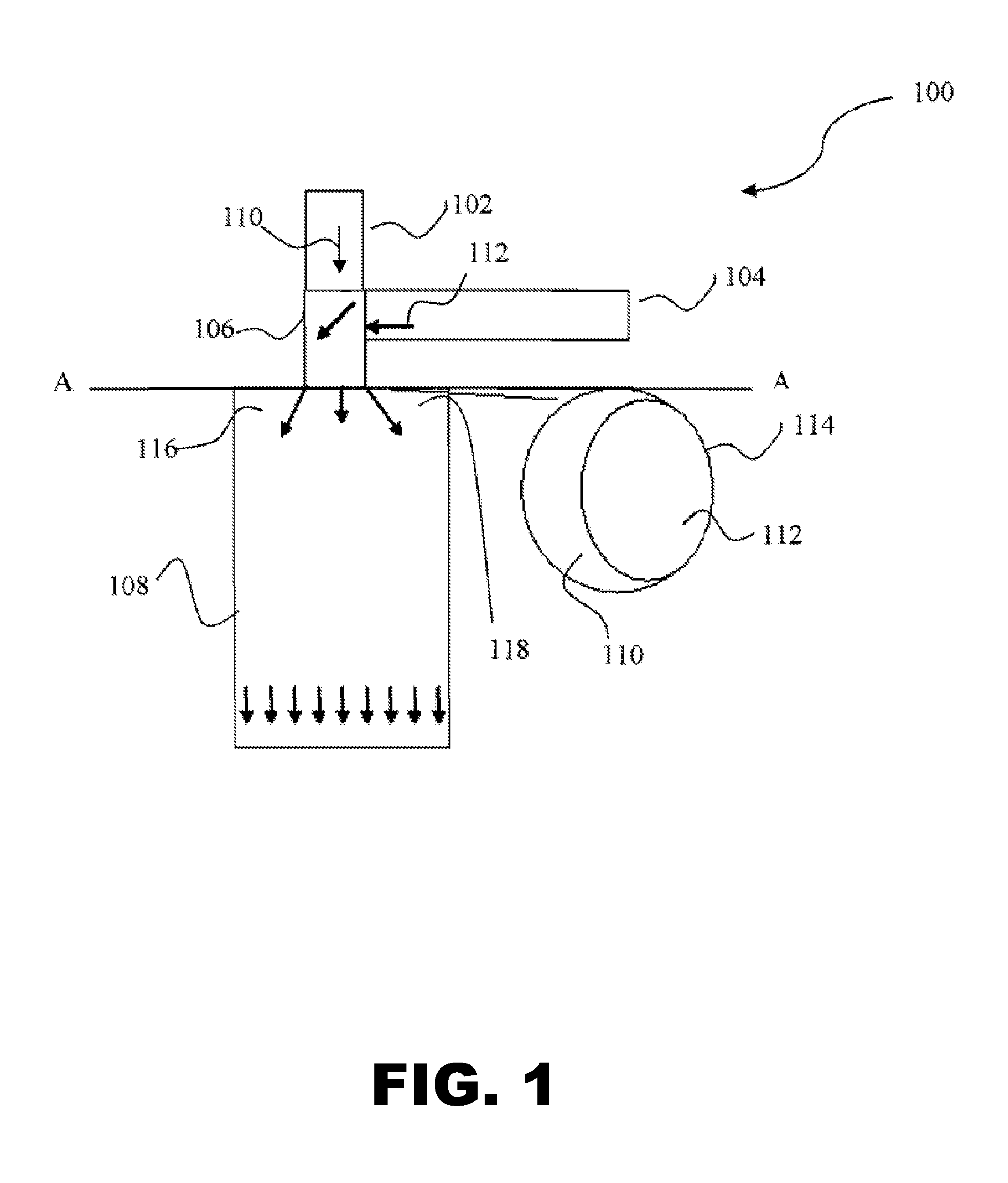
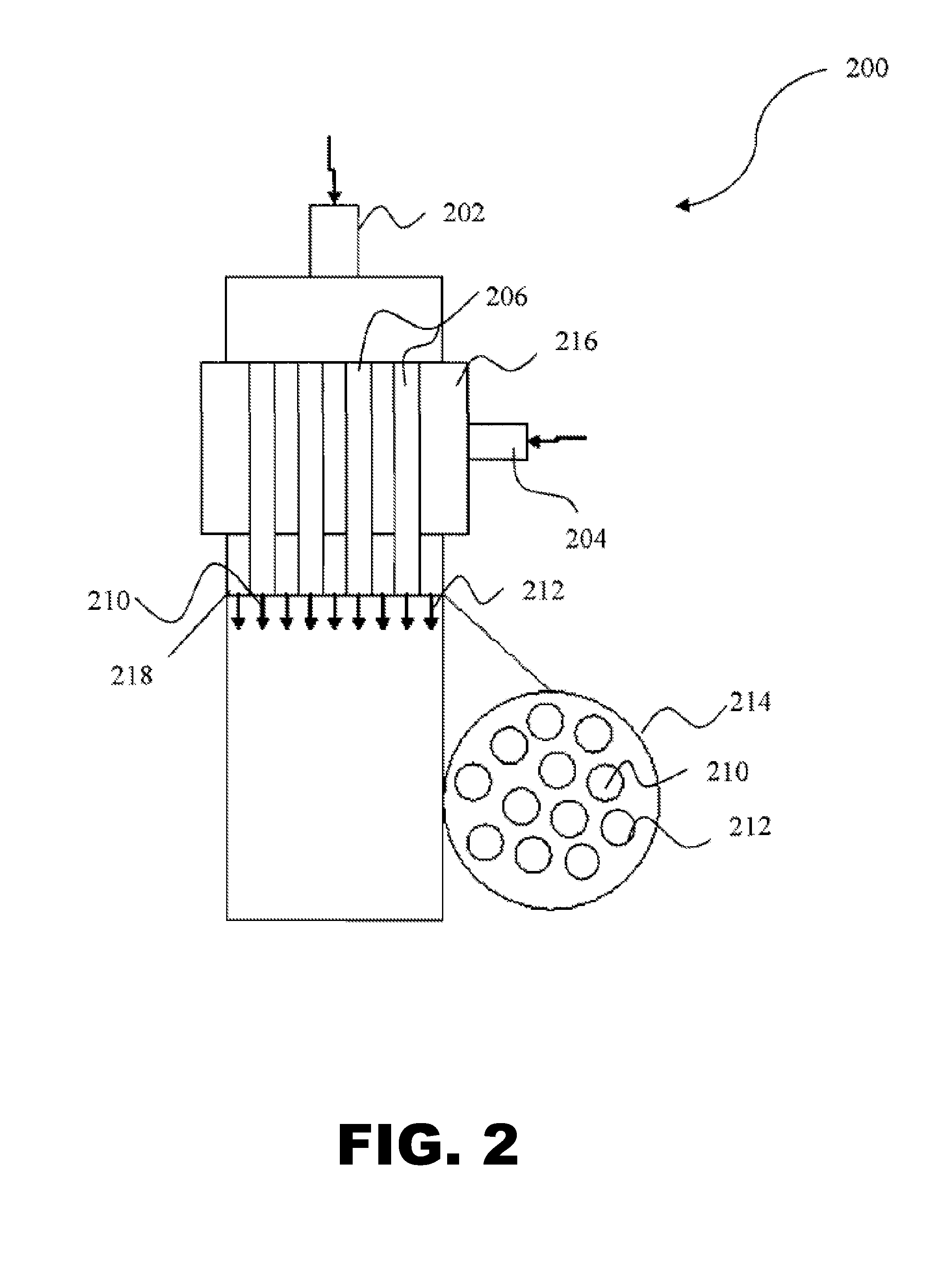
[0057]For this example, perchloroethylene and methyl chloride are reacted in the presence of the initiator carbon tetrachloride to provide 1,1,2,3-tetrachloropropene in a reactor comprising both a design that allows the production rate to be adjusted by controlling the temperature of the reactor effluent and a design that facilitates reduced backmixing prior to entry into the adiabatic plug flow reactor. More particularly, the reactor comprises a mixer having the design shown in FIG. 2, and, separate evaporators for the perchloroethylene and methyl chloride.

[0058]Perchloroethylene will be introduced into a 6 foot internal diameter tubular reactor at a temperature of about 325° C. and a feed rate of about 2.65 MM# / day. Methyl chloride will be fed at a rate of 2.01 MM# / day and a temperature of 430° C., while carbon tetrachloride will be provided to the reactor at a feed rate of 0.25 MM# / day and at a temperature of 325° C. Because the perchloroethylene is set at a lower temperature tha...

example 3

[0059]For this example, perchloroethylene and methyl chloride are reacted in the presence of the initiator carbon tetrachloride to provide 1,1,2,3-tetrachloropropene in a reactor comprising both a design that allows the production rate to be adjusted by controlling the temperature of the reactor effluent and a design that facilitates reduced backmixing and / or recirculation prior to entry into the adiabatic plug flow reactor. More particularly, the reactor utilized comprises a mixer having the design shown in FIG. 2, and, separate evaporators for the perchloroethylene / carbon tetrachloride and methyl chloride.

[0060]Methyl chloride, perchloroethylene and carbon tetrachloride were fed to a 2″ ID Inconel 600 reactor at the rate of 3500-4500 SCCM, 1400-17000 SCCM, and 700-980 SCCM respectively to achieve about 30-40 seconds residence time at 260 psig.

[0061]The reactor is equipped with the mixer shown in FIG. 2. The methyl chloride stream was preheated to from about 340° C. to about 370° C...

example 4

[0062]Chlorinated and / or fluorinated propenes having the formula CH2-c-gClcFg═CH1-d-hCldFh—CH3-e-fCleFf wherein c is 0-2, d is 0-1, e is 0-3, f is 0-3, and g is 0-2 while c+g≦2, d+h≦1, and e+f≦3 are prepared using a reactor having a design that minimizes heat transfer to and / or from the reactor, and in accordance with Examples 2 and 3. With overall reactor volume similar to that described in Example 2, Table 1 shows that at least 10 cm insulation with effective thermal conductivity of 0.05 W / M / ° C. is expected to maintain reagent conversion close to 10% in a reactor with 6 ft ID.

[0063]Table 1 also shows that removing the insulation, leaving the reactor metal wall of Inconel results in an effective thermal conductivity of 20 W / M / ° C. and this is expected to drop the conversion or productivity by more than 50% if the same reactor length is used. Reducing the reactor diameter to 1 ft keeping the same reactor volume and insulation thickness the same results in about 10% drop in reactor ...


PUM

PropertyMeasurementUnit
Reynolds numberaaaaaaaaaa
inlet temperatureaaaaaaaaaa
diameteraaaaaaaaaa

Abstract

The present invention provides adiabatic plug flow reactors suitable for the production of chlorinated and / or fluorinated propene and higher alkenes from the reaction of chlorinated and / or fluorinated alkanes and chlorinated and / or fluorinated alkenes. The reactors comprise one or more designs that minimize the production of by-products at a desired conversion.

Description

FIELD[0001]The present invention relates to plug flow reactors capable of adiabatic operation and suitable for conducting continuous, gas phase, free radical reactions to produce chlorinated and / or fluorinated propene and higher alkenes. Processes incorporating the same are also provided.BACKGROUND[0002]Tubular reactors are ubiquitous in the manufacture of commodity chemicals, in particular in processes wherein continuous operation is desired or required. The ideal flow condition in a tubular reactor is ‘plug flow’, and under such ideal conditions, the residence time in the reactor is the same for all elements of fluid and there is typically a uniform velocity profile across the radius of the reactor. Product mixing is also ideally limited to material the same age, i.e. mixing occurs in the radial direction only. That is, as the plug flows through the reactor, the plug components are perfectly mixed in the radial direction, with mixing in the axial direction being nonexistent.[0003]...

Claims


Application Information

Patent Timeline
Patent Type & Authority Applications(United States)
IPC IPC(8): C07C17/20B01J19/00C07C17/269B01J19/24B01F23/10
CPCC07C17/206B01J19/2415B01J19/2405B01J2219/00247C07C17/269B01J2219/00054B01J19/0013B01J4/00B01J19/00B01J2204/002B01J2219/00155C07C21/04C07C21/18B01J19/0026B01J19/006B01J2219/00063B01J2219/00162B01J2219/00166B01J19/24
Inventor TIRTOWIDJOJO, MAX M.BAI, HUACHAKRABORTY, DEBASHISEIFFLER, JUERGENGROENEWALD, HEINZHIRSEKORN, KURT F.KOKOTT, MANFREDKRUPER, WILLIAM J.LUEBBE, THOMAS U.PARSONS, THOMAS J.PATEL, AVANI MAULIKWOBSER, MARCUS
Owner BLUE CUBE IP
Why Eureka
Try Eureka