Optical transducer for detecting liquid level

a technology of optical transducers and liquid levels, which is applied in the direction of optical radiation measurement, instruments, machines/engines, etc., can solve the problems of difficult construction of compact optical transducers capable of operating through, and the above-described type of liquid level transducers can produce erroneous signals, so as to minimize heat transfer between liquid in the reservoir and light source and photosensor

Inactive Publication Date: 2005-10-27
OPTI SENSOR SYST
View PDF29 Cites 18 Cited by
  • Summary
  • Abstract
  • Description
  • Claims
  • Application Information

AI Technical Summary

Benefits of technology

[0007] According to yet a further aspect of the invention, an optical transducer for determining the presence or absence of liquid in a reservoir comprises a housing with a hollow interior and a mounting section with external threads for engagement with internal threads of a reservoir. The optical transducer also comprises an optical probe that extends through the housing with a proximal end of the optical probe being positioned in the hollow interior above the mounting section and a distal end of the optical probe being positioned outside of the housing below the mounting section. It will be understood that terms of position and / or orientation as may be used throughout the specification and claims, such as “above” and “below” refer to relative, rather than absolute positions and / or orientations. A light source is positioned in the hollow interior above the proximal end for projecting radiant energy into the optical probe toward the distal end. A photosensor is also positioned in the hollow interior above the proximal end for detecting radiant energy reflected from the distal end to thereby detect the presence and absence of liquid on the optical probe. In this manner, heat transfer between liquid in the reservoir and the light source and photosensor is minimized.

Problems solved by technology

However, it has been found that liquid level transducers of above-described type can produce erroneous signals.
In addition to the above, it has previously been difficult to construct a compact optical transducer that is capable of operating through a wide temperature range due to the relative proximity of the light source and photosensor to the liquid being measured.

Method used


Image

  • Optical transducer for detecting liquid level
  • Optical transducer for detecting liquid level
  • Optical transducer for detecting liquid level

Examples


Embodiment Construction

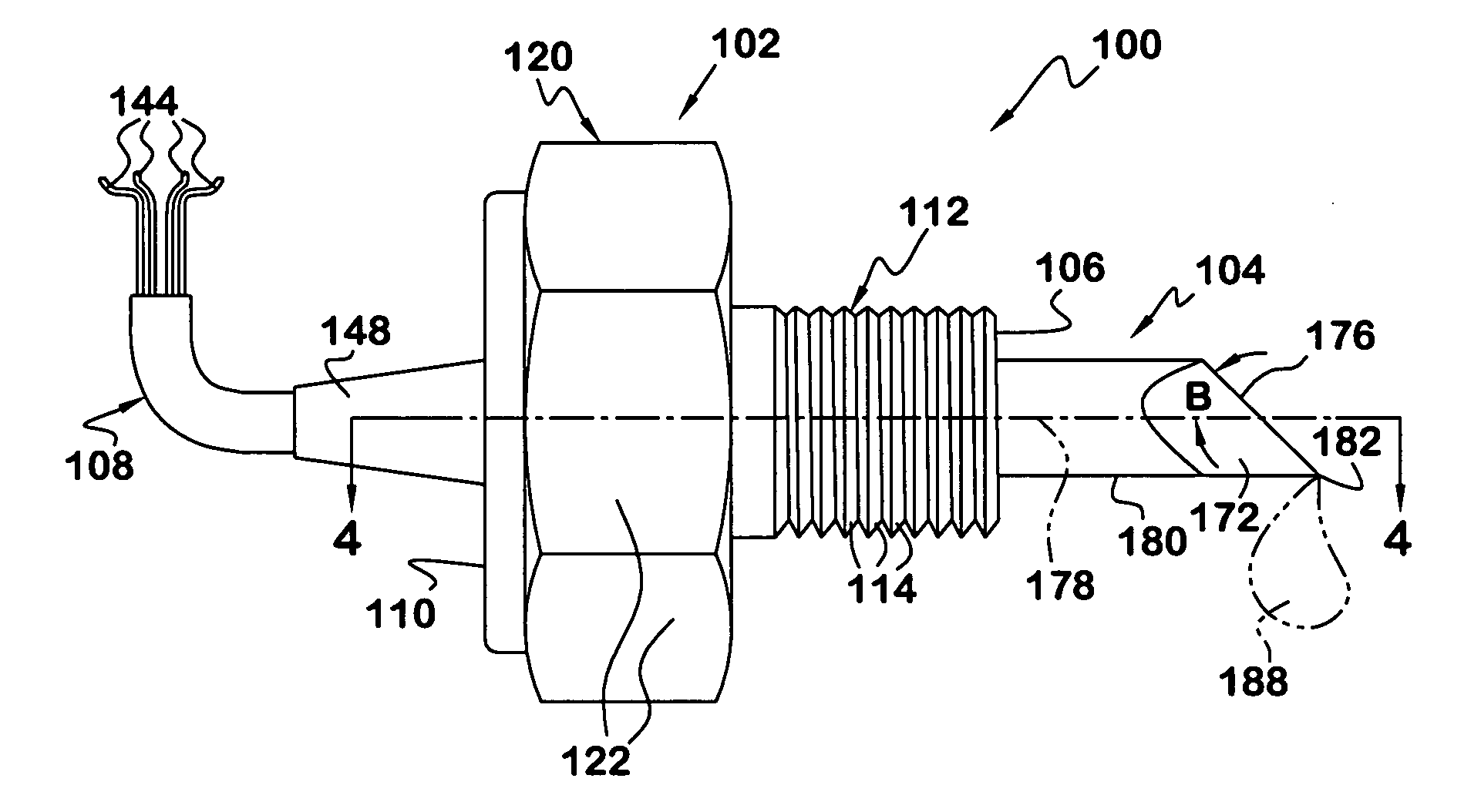
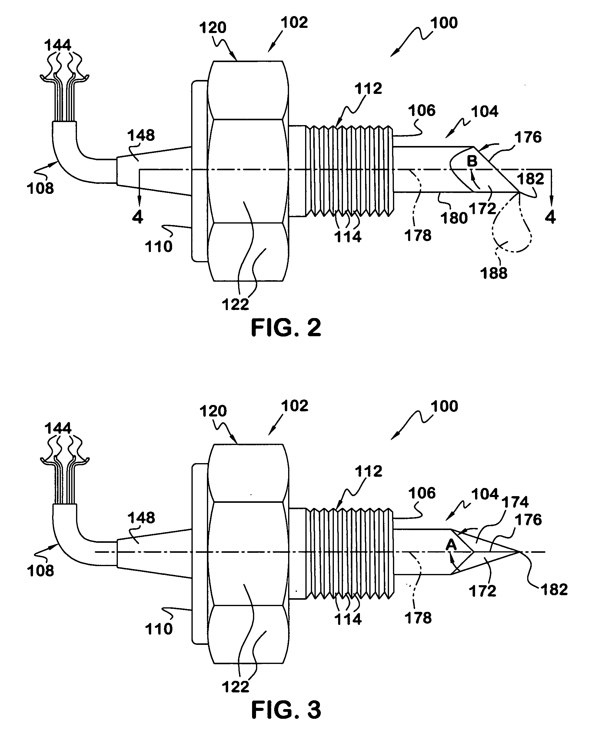
[0018] Referring to the drawings and to FIGS. 2 and 3 in particular, an optical liquid level transducer 100 in accordance with the present invention is illustrated. The optical transducer 100 preferably includes a housing 102, an optical probe 104 extending from a distal end 106 of the housing 102, and a wiring harness 108 extending from an opposite proximal end 110 of the housing.

[0019] With additional reference to FIGS. 4 and 5-6, the housing 102 is preferably constructed of a metal material, such as brass. The housing 102 includes a mounting section 112 with external threads 114 for engagement with internal threads 116 of a reservoir housing 118, which may be in the form of a tank, vessel, container or the like. The housing 102 also preferably includes a securing section 120 with generally flat, external faces 122 for engagement by a wrench or the like (not shown) for installing and removing the optical liquid level transducer 100 with respect to the reservoir housing 118 in a w...


PUM

PropertyMeasurementUnit
anglesaaaaaaaaaa
refractive indexaaaaaaaaaa

Abstract

An optical transducer for determining the presence or absence of liquid or the like in a reservoir includes a housing with a hollow interior and an optical probe that extends through the housing. The optical probe has a central axis, a proximal end positioned in the hollow interior and a distal end positioned outside of the housing. The distal end has first and second measurement surfaces that intersect at a transverse edge. The transverse edge extends at an acute angle with respect to the central axis. A light source is arranged for projecting radiant energy into the optical probe toward the distal end. A photosensor is arranged for detecting radiant energy reflected from the distal end to thereby detect the presence and absence of liquid on the optical probe.

Description

BACKGROUND OF THE INVENTION [0001] This invention relates to optical transducers, and more particularly to optical transducers for detecting liquid level and the like. [0002]FIGS. 1A-1C schematically depict a prior art optical transducer 10 for determining liquid level in tanks, vessels or the like. As shown, the transducer 10 includes an optical body 12 with a conical tip 14 at one end thereof, and a light source 16 and photosensor 18 at an opposite end thereof. In the absence of liquid as shown in FIG. 1A, light from the light source 16 is normally projected through the optical body 12 where it is internally reflected at a conical measuring surface 20 of the conical tip 14 and returns to the photosensor 18, as represented by arrow 22. When the conical tip 14 is submerged in liquid, as represented by dashed line 24 in FIG. 1B, the light is refracted out of the conical tip 14 and into the liquid (arrow 26). The amount of light at the photosensor 18 is thus significantly diminished. ...

Claims


Application Information

Patent Timeline
Patent Type & Authority Applications(United States)
IPC IPC(8): G01B9/00G01F23/292G01N15/06G01N21/49G01N21/85
CPCG01F23/2925
Inventor WIRTHLIN, ALVIN R.
Owner OPTI SENSOR SYST
Why Eureka
Try Eureka