Compact-type discharge lamp

a discharge lamp and compact technology, applied in the direction of discharge tube/lamp details, discharge tube luminescnet screens, electric discharge lamps, etc., can solve the problems of not being able to use general metallic filament bulbs for light equipment, temperature inside the ballast housing is increased to an extremely high level, etc., to achieve the effect of minimizing heat transfer between the discharge tube and the ballas

Inactive Publication Date: 2006-11-02
KANG SEONG JIN
View PDF8 Cites 10 Cited by
  • Summary
  • Abstract
  • Description
  • Claims
  • Application Information

AI Technical Summary

Benefits of technology

[0008] In order to solve the problems above, it is an object of the present invention to provide a discharge lamp with a discharge tube detachable, wherein a part at which a discharge tube and a ballast are mechanically coupled is minimized so that the heat transfer between the discharge tube and the ballast can be minimized.

Problems solved by technology

However, in the general light-bulb-type discharge lamp, since the discharge tube, the ballast housing of a peaked hat in shape and the base member are joined in a line so that its length becomes considerably long in comparison to a general metallic-filament bulb, it has a defect that it cannot be used for light equipment for a general metallic-filament bulb.
However, since the discharge lamp in accordance to U.S. Pat. No. 5,541,477 adopts a structure, in which the discharge tube and the ballast housing are joined in the screw-in base structure commonly, has a problem that the entire discharge lamp has to be disposed in case either of the discharge tube or the ballast housing has a defect.
Accordingly, the temperature inside the ballast housing increases up to an extremely high level due to the heat transfer, and consequently there's a problem that circuit elements included in the ballast become deteriorated.

Method used


Image

  • Compact-type discharge lamp
  • Compact-type discharge lamp
  • Compact-type discharge lamp

Examples


Embodiment Construction

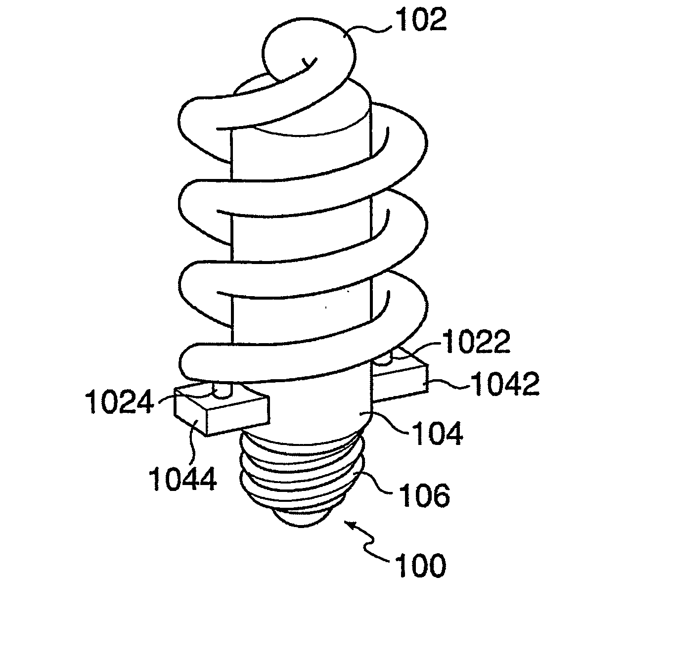
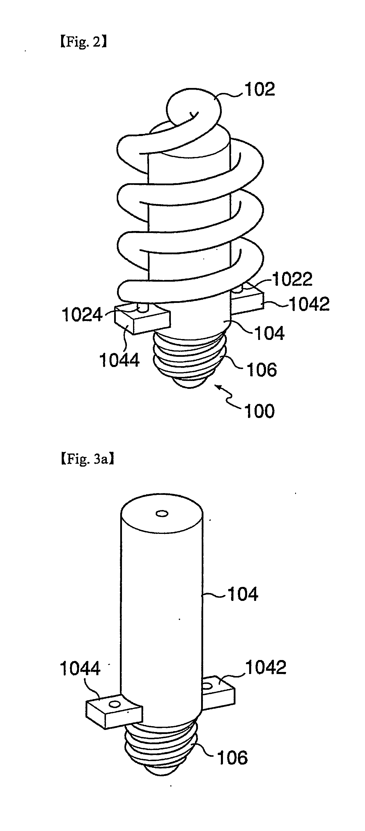
[0021] Hereinafter, exemplary embodiments of the present invention will now be described in detail with reference to attached drawings. First, with reference to FIG. 2, FIG. 2 shows a compact-type discharge lamp according to an exemplary embodiment of the present invention schematically. As shown in FIG. 2, a discharge lamp 100 according to the present embodiment includes a discharge tube 102 formed of a transparent material such as glass, quartz or the like with a space in its center, including electrodes 1022 and 1024 for electricity supply, a ballast housing 104 formed to be inserted into the space of the discharge tube, for containing a ballast to supply electricity to the discharge tube 102 and initiate and continue a discharge of electricity, including coupling members 1042 and 1044 coupled to the electrodes 1022 and 1024 of the discharge tube 102, and a base member 106 coupled to a first end of the ballast housing 104 to supply electricity to the ballast contained in the ball...


PUM


Abstract

The present invention provides a compact-type discharge lamp which can be used in a socket for an incandescent lamp, wherein the compact-type discharge lamp includes a discharge tube which is detachably inserted into a receptacle formed on a ballast housing.

Description

TECHNICAL FIELD [0001] The present invention relates to a discharge lamp, and more particularly to a compact-type discharge lamp, wherein a ballast housing, which contains a ballast for driving the discharge lamp, and a base member are integrally formed. [0002] A discharge lamp is widely used for lighting equipment. Generally, a discharge lamp includes a discharge tube of transparency formed of a transparent material such as glass or quartz and a ballast for driving the discharge lamp. Discharge gases such as mercury vapor and a buffer gas are inserted into the discharge tube to cause a discharge of electricity and the discharge tube is sealed. When the discharge tube is supplied with electricity from the outside by the ballast, a discharge of electricity occurs by the discharge gas inside the discharge tube, and then plasma is generated so that ultraviolet rays, visible rays or the like are emitted. A fluorescent lamp, a kind of the discharge lamp, wherein a fluorescent material is...

Claims


Application Information

Patent Timeline
Patent Type & Authority Applications(United States)
IPC IPC(8): H01J1/62H01J61/32H01J61/54H01J61/30H01J61/56
CPCH01J61/327H01J61/56H01J61/54H01J61/30
Inventor KANG, SEONG-JIN
Owner KANG SEONG JIN
Why Eureka
Try Eureka