Boiler flue gas purifying and heat exchanging device and application method thereof

A technology of heat exchange device and boiler flue gas, which is applied in the direction of chemical instruments and methods, combined devices, separation methods, etc., which can solve the problem of insufficient contact between flue gas and spray water for heat exchange, inability to purify flue gas at the same time, complex equipment, etc. problems, to achieve the effect of improving waste heat utilization efficiency, preventing heat loss, and reducing heat loss

Inactive Publication Date: 2016-07-13
JIANGSU JINYUAN TENGFENG HEAT EXCHANGE EQUIP CO LTD
View PDF8 Cites 10 Cited by
  • Summary
  • Abstract
  • Description
  • Claims
  • Application Information

AI Technical Summary

Problems solved by technology

[0003] The existing direct contact flue gas waste heat recovery device does not have a bubbling type, but only uses simple spraying, or a simple herringbone water baffle, so that the flue gas and the spraying water cannot fully contact and exchange heat, and the flue gas cannot be purified at the same time. gas, additional flue gas purification equipment is required, the equipment is complicated, the project is huge, and the cost is high

Method used


Image

  • Boiler flue gas purifying and heat exchanging device and application method thereof

Examples


Embodiment

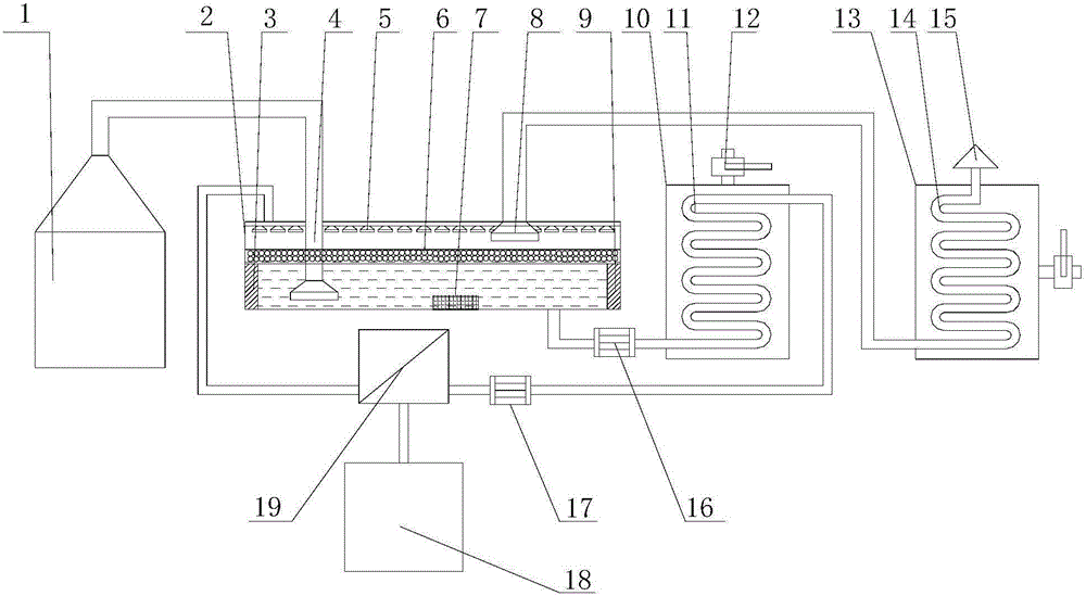
[0042] A boiler flue gas purification heat exchange device in this embodiment, such as figure 1 As shown, it includes a boiler 1, a flue gas purification chamber 2, a first heat exchanger 10, a second heat exchanger 13 and a reverse osmosis membrane group 19; the boiler 1 communicates with the smoke inlet of the flue gas purification chamber 2 through a flue gas pipeline , the smoke outlet of the flue gas purification chamber 2 communicates with the second heat exchanger 13 through a flue gas pipeline, the liquid outlet of the flue gas purification chamber 2 communicates with the first heat exchanger 10 through a pipeline, and the first heat exchanger 10 It communicates with the reverse osmosis membrane group 19, and the reverse osmosis membrane group 19 communicates with the liquid inlet of the flue gas purification chamber 2.

[0043] The flue gas purification chamber includes a shell, a smoke inlet pipe 4, a DC power supply (not shown in the figure), a cathode electrode 9, ...


PUM

PropertyMeasurementUnit
thicknessaaaaaaaaaa

Abstract

The invention relates to a boiler flue gas purifying and heat exchanging device. The boiler flue gas purifying and heat exchanging device comprises a boiler, a flue gas purifying chamber, a first heat exchanger, a second heat exchanger and a reverse osmosis membrane set, wherein the boiler is communicated with a flue inlet in the flue gas purifying chamber through a flue gas pipeline, a flue gas outlet in the flue gas purifying chamber is communicated with the second heat exchanger, a liquid outlet in the flue gas purifying chamber is communicated with the first heat exchanger, the first heat exchanger is communicated with the reverse osmosis membrane set, and the reverse osmosis membrane set is communicated with a liquid inlet in the flue gas purifying chamber; the flue gas purifying chamber comprises a casing, a flue inlet pipe, a DC power supply, a negative electrode, a positive electrode, an activated carbon layer and a flue exhausting pipe; circulation liquid is stored in the casing; a coil pipe is arranged on the first heat exchanger, a heat exchanging flue pipe is arranged on the second heat exchanger, and an outlet in the heat exchanging flue pipe is communicated with a chimney. According to the boiler flue gas purifying and heat exchanging device disclosed by the invention, when flue gas is purified through the flue gas purifying chamber, the circulation liquid in the flue gas purifying chamber directly performs heat exchange with the flue gas; the circulation liquid is in direct contact with the flue gas, so that the heat exchanging efficiency is high, and the heat loss is low.

Description

technical field [0001] The invention relates to a boiler flue gas purification heat exchange device and an application method thereof, and belongs to the technical field of flue gas purification waste heat utilization. Background technique [0002] With the rapid development of my country's economy, the energy consumption is increasing day by day, and the air quality is also getting worse day by day. Today, as the requirements for energy conservation, emission reduction and environmental protection continue to increase, natural gas, as a clean energy source with high calorific value, continues to increase its proportion in my country's urban energy consumption structure. At present, most coal-fired boilers in large and medium-sized cities in my country have been changed to gas-fired boilers. For most gas-fired boilers, the exhaust gas temperature is still above 150°C, even as high as 250°C. The gas-fired boiler flue gas contains about 18% water vapor (volume percentage), a...

Claims


Application Information

Patent Timeline
Patent Type & Authority Applications(China)
IPC IPC(8): B01D53/32B01D53/02B01D50/00B01D53/78B01D53/40F28D7/04F28F21/08
CPCB01D50/00B01D53/02B01D53/326B01D53/40B01D53/78B01D2258/0283F28D7/04F28F21/085F28F21/086
Inventor 李明祥朱冬宏陈道祥
Owner JIANGSU JINYUAN TENGFENG HEAT EXCHANGE EQUIP CO LTD
Why Eureka
Try Eureka