Continuous thermal decomposition method and apparatus for sludge

A technology of thermal decomposition and sludge, applied in pyrolysis sludge treatment, dehydration/drying/concentrated sludge treatment, special form of dry distillation, etc. High temperature and other problems, to achieve the effect of small heat loss and avoid air pollution

Inactive Publication Date: 2015-10-21
李学文
View PDF3 Cites 18 Cited by
  • Summary
  • Abstract
  • Description
  • Claims
  • Application Information

AI Technical Summary

Problems solved by technology

The existing drying system uses open fire and hot air to dry, and a large amount of fine dust is generated during the drying process, especially in the drying and discharging process, the fan generates a large amount of fine dust above PM100, which causes a lot of pollution to the environment
The existing carbonization host uses a screw propeller, which is difficult to withstand the high temperature above 700°C required for complete carbonization, and it is difficult to maintain a continuous and stable operating state
The existing sludge thermal decomposition method adopts a circulating water cooling system. Since the carbon output temperature can reach above 500°C, a large amount of circulating cold water is required to reduce the temperature, and the energy consumption and mechanical consumption are large.

Method used


Image

  • Continuous thermal decomposition method and apparatus for sludge
  • Continuous thermal decomposition method and apparatus for sludge

Examples


Embodiment Construction

[0037] The principles and features of the present invention are described below in conjunction with the accompanying drawings, and the examples given are only used to explain the present invention, and are not intended to limit the scope of the present invention.

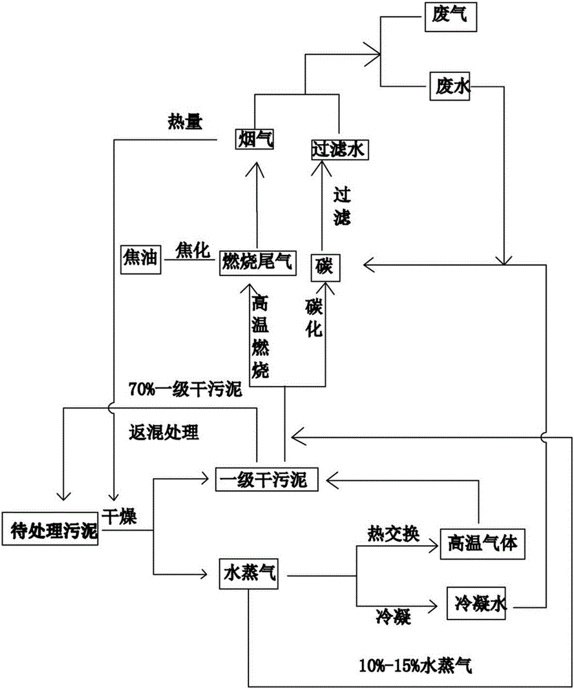
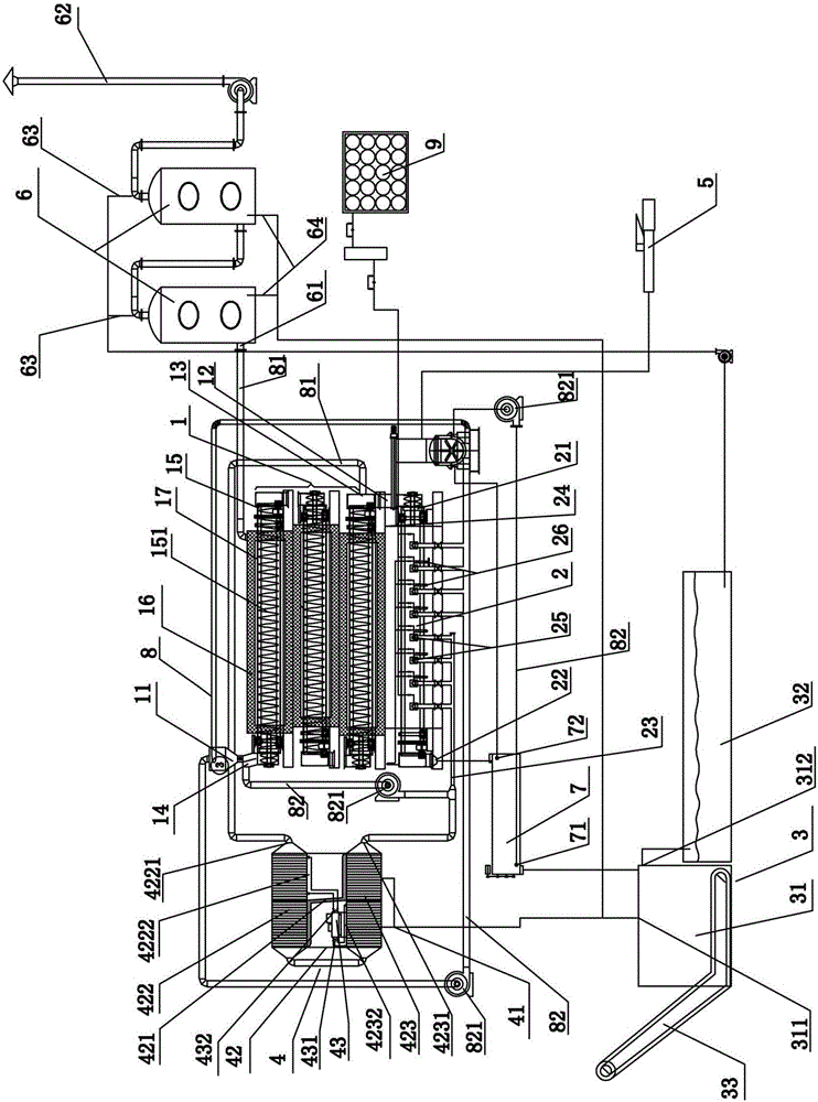
[0038] like figure 1 Shown, a kind of continuous sludge pyrolysis method is characterized in that, comprises the following steps:

[0039] Step 1) Drying process: Stir the sludge to be treated with a moisture content of 80%-90% in the conveying device evenly and then transfer it to the drying kiln. Internally dried to a water content of 10%-30%, forming a first-level dry sludge and generating high-temperature water vapor, the first-level dry sludge is divided into two parts, which are the sludge to be carbonized and accounting for 20%-40% of the total weight Circulating sludge with a total weight of 60%-80%; return the circulating sludge to the conveying device and mix it with the sludge to be treated to form secon...


PUM

PropertyMeasurementUnit
water contentaaaaaaaaaa

Abstract

The invention relates to a continuous thermal decomposition method and apparatus for sludge. The method comprises the following steps: drying and carbonization: a step of drying and carbonizing to-be-treated sludge at negative pressure; heat exchange and recovery: a step of subjecting high-temperature water vapor produced in the drying process of the sludge to heat exchange and condensation, recovering heat, applying the recovered heat to drying, adsorbing and filtering condensed water with carbon produced by carbonization and then recovering the treated condensed water for cyclic utilization; and treatment of combustion tail gas: a step of cooling flue gas produced by carbonization with the outer wall of a drying system, washing the flue gas with the condensed water, discharging the washed flue gas and subjecting waste water produced in washing to adsorption and impurity removal by carbon produced by carbonization of the sludge so as to form filtered water for cyclic utilization. The continuous thermal decomposition method for the sludge makes full use of heat and products produced in drying and carbonization of the sludge, recovers the heat and cyclically applies the recovered heat to drying and carbonization of the sludge, so a self-sufficient heat energy supply system is established, and no extra energy is consumed; thus, the method is energy-saving and environment-friendly.

Description

technical field [0001] The invention relates to the technical field of sludge treatment, in particular to a continuous sludge thermal decomposition system. Background technique [0002] With the acceleration of the urbanization process, the output of municipal sludge is also increasing substantially. The composition of sludge is very complex, including organic matter, inorganic matter, microorganisms, heavy metals, salts, etc. [0003] In the prior art, the material flow in the municipal sludge treatment system can be divided into four categories: sludge flow, hot air flow, air flow and water flow. In the existing method, the dewatered sludge with a moisture content of about 80% first passes through the sludge hopper and enters the drying furnace. The initial sludge is dried in the drying furnace to a moisture content of 30% and then sent to the carbonization furnace by a conveyor belt. Carbonization, and then the carbonized sludge is sent to the cooling tower by the convey...

Claims


Application Information

Patent Timeline
Patent Type & Authority Applications(China)
IPC IPC(8): C02F11/10C02F11/12C02F1/28C10B53/00C10B57/10
Inventor 李学文林常婧
Owner 李学文
Why Eureka
Try Eureka