High temperature rotating union

a high-temperature rotating union and assembly technology, applied in the direction of bearing cooling, lighting and heating apparatus, liquid/gas/vapor treatment of indefinite length materials, etc., can solve the problems of limiting the use of such bearing structures to application temperatures, poor lubricant, and limited temperature range of ball bearing assemblies, so as to facilitate air circulation, facilitate cooling of the bearing assembly portion, and minimize heat transfer

Inactive Publication Date: 2000-12-26
DEUBLIN
View PDF3 Cites 17 Cited by
  • Summary
  • Abstract
  • Description
  • Claims
  • Application Information

AI Technical Summary

Benefits of technology

It is another object of the present invention to provide a rotary union assembly having an insulating air pocket within the rotating rotor to provide and facilitate the cooling of the bearing assembly portion of the rotary union assembly.
It is a further object of the present invention to provide a rotary union assembly having structural fins integral and structurally arranged on the rotating rotor which facilitates air circulation to the bearing structure or portion of the rotary union to thereby minimize and maintain the bearing temperature within the operating conditions of the bearing structure.
It is yet another object of the present invention to provide a rotary union assembly having a radially and axially positioned bearing assembly which is spaced from the rotor to minimize the transfer of heat from the rotor union to the bearing assembly.

Problems solved by technology

However, such ball bearing assemblies are limited to a maximum temperature range of about 125.degree. C. because of the thermal instability of the standard bearing materials above such temperatures.
Also, when ball bearings assemblies are utilized as the rolling bearing structure within a rotary union, the ball bearing assembly must be grease lubricated which effectively limits the use of such bearing structures to application temperatures dictated by the bearing temperature limitations.
Additionally, such ball bearing assemblies can be lubricated by the heat transfer oil, which is a relatively poor lubricant, and require that the assembly include at least dual bearing structures to provide support for the rotating rotor in the rotating union.
Accordingly, such bearing structures are expensive and space consuming.
Thus, when it is desired to provide rotating union assemblies capable of use at high temperatures and which include a simplified structure, such bearing assemblies have found limited application.

Method used


Image

  • High temperature rotating union
  • High temperature rotating union
  • High temperature rotating union

Examples


Embodiment Construction

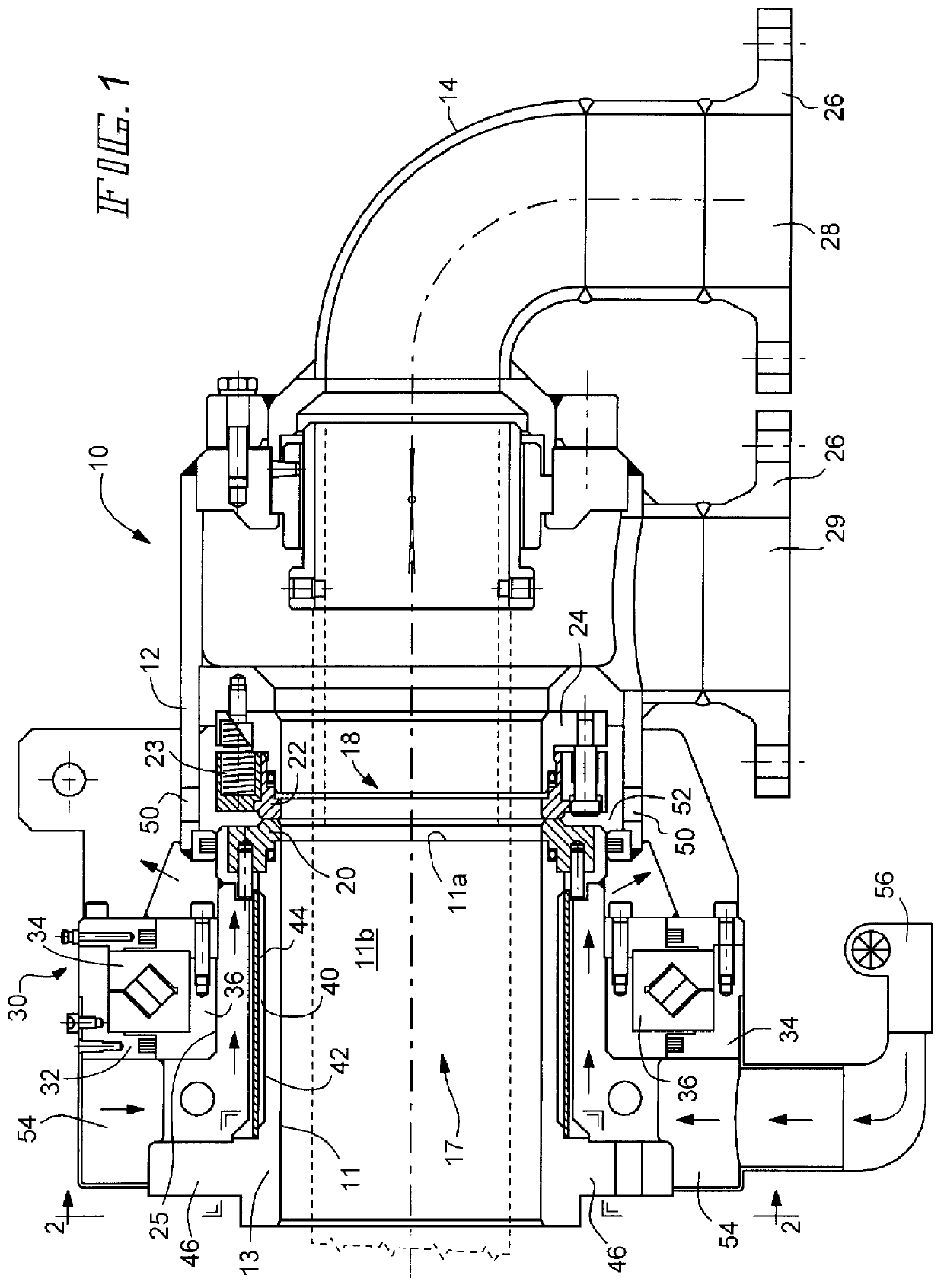
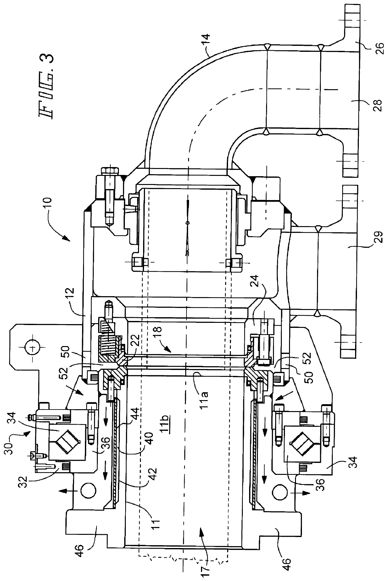
Referring to FIG. 1, there is illustrated a duoflow rotating union or joint assembly 10 which is designed for coupling a fluid source to a rotating drum or a calendaring roller (not shown). The rotating union assembly 10 includes a cylindrical housing 12, an end cap or head member 14, a tubular rotor member 11, a rotor bearing assembly 30 and a mechanical face seal assembly 18. The mechanical face seal assembly 18 is comprised of a rotating face seal member 20 secured to the end 11a of the tubular rotor 11 and a second non-rotating seal member 22 mounted to a carrier sleeve assembly 24 which is axially moveable within the housing 12 between a first position wherein the second seal member is spaced from the first seal member and a second position wherein the second seal member and the first seal member are engaged together to provide a seal between the rotor and the carrier. The tubular rotor 11 has an axial discharge bore or passageway 17 therethrough.

The rotor bearing assembly 30 i...


PUM


Abstract

A rotating union has a plurality of fin members spaced about and extending radially outwardly from the rotor to provide an air circulation between the rotor and the bearing assembly to cool the bearing assembly. Additionally, the rotor may include a circumferential annual recess in the rotor outer wall which is enclosed by an annular sealing member to provide an air pocket or gap which insulates the bearing assembly from the hot fluid flowing through the rotating unions.

Description

The present invention relates to rotating union coupling devices which have particular application in high temperature environments employing steam, hot water and hot oil applications.Rotating unions have been used extensively in the paper, plastic and textile processing industries to couple the outlet of a fluid source to rotating drums or cylindrical rolls or to open gear paper machines. In known rotary unions utilized in coupling fluid sources to such rotating devices, the rotary unions utilize either carbon journal bearings or dual ball bearing structures to absorb and maintain the alignment of the rotor and the load of the joint assembly. However, such ball bearing assemblies are limited to a maximum temperature range of about 125.degree. C. because of the thermal instability of the standard bearing materials above such temperatures. Also, when ball bearings assemblies are utilized as the rolling bearing structure within a rotary union, the ball bearing assembly must be grease ...

Claims


Application Information

Patent Timeline
Patent Type & Authority Patents(United States)
IPC IPC(8): F16C37/00D21F5/02D06B5/10D21G1/02F16C19/16F16C19/36F16L27/08
CPCF16C37/007F16C19/362Y10T137/6579Y10T137/6525Y10T137/86268
Inventor BETTI, BRUNO
Owner DEUBLIN
Why Eureka
Try Eureka