

Method and Apparatus for Monitoring Bodily Analytes
- Summary
- Abstract
- Description
- Claims
- Application Information
AI Technical Summary
Benefits of technology
Problems solved by technology
Method used
Image

Examples
embodiment 2000
[0089]In FIG. 6, the embodiment 2000 may use a wideband source of radiation 2, emitting light provided by, but not limited to, white LEDs or a cluster of narrowband IR LEDs of different wavelengths, switched on as desired, each one alone, or in selected groups, or all together.
[0090]Alternative embodiments may sense the absorption spectrum by using a detection unit 28 with a single wideband sensor, in association with a source of radiation 2 emitting multiple wavelengths. By way of example, diode lasers having a plurality of wavelengths may be used, or IR LEDs of different wavelengths switched on one at a time, or in combination. Either way, finding the effective absorption coefficient at different wavelengths yields the absorption spectrum of the sample under examination, from which the concentration of the analytes, or fluid ingredients can be deduced using standard statistic methods, on the basis of the known absorption spectrum of the analytes.
[0091]An embodiment implementing a ...
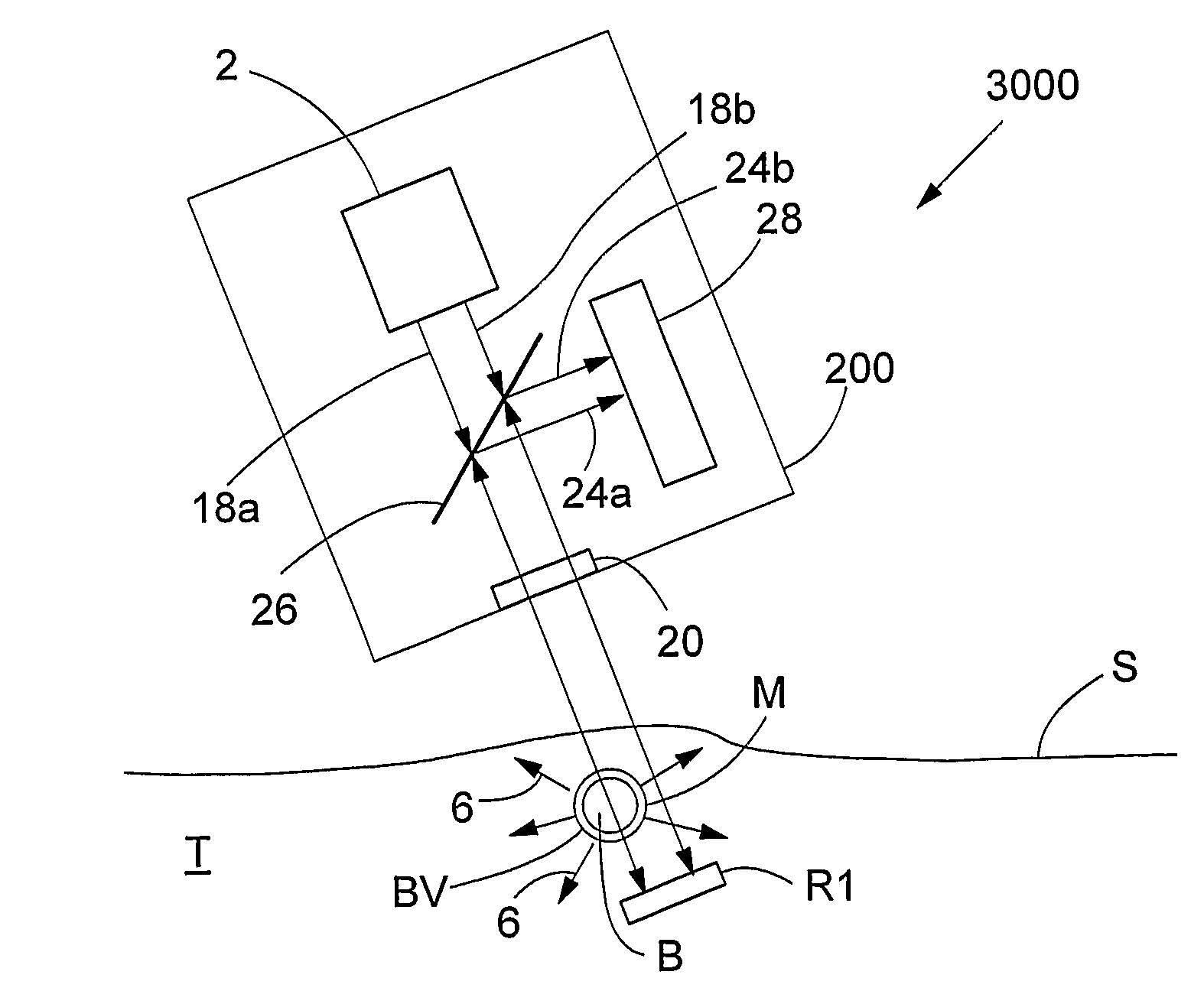
embodiment 3000
[0096]FIG. 8 is a schematic rendering of a further embodiment 3000 shown with incoming radiation divided into two parallel beams of light. Although not shown in the Figs., the same embodiment is adaptable to operate with more than two beams of light by configuring the source of radiation 2 to emit the desired number i of beams, and by configuring the sensor(s) 8 of the detection unit 28 as either, but not shown in FIG. 8, a single wideband sensor 80, or as a plurality of i narrowband sensors 8i.
[0097]FIG. 8 depicts an example of a data sampler 200 utilizing two parallel beams of light to obtain the differential absorption spectrum resulting from a first absorption spectrum derived from the incoming radiation crossing the skin S, tissue T, and blood vessel BV, and from a second absorption spectrum derived from the impinging radiation passing only through the skin S and tissue T. Each beam thus crosses different bodily matter.
[0098]The light source 2 emits two identical incoming coll...
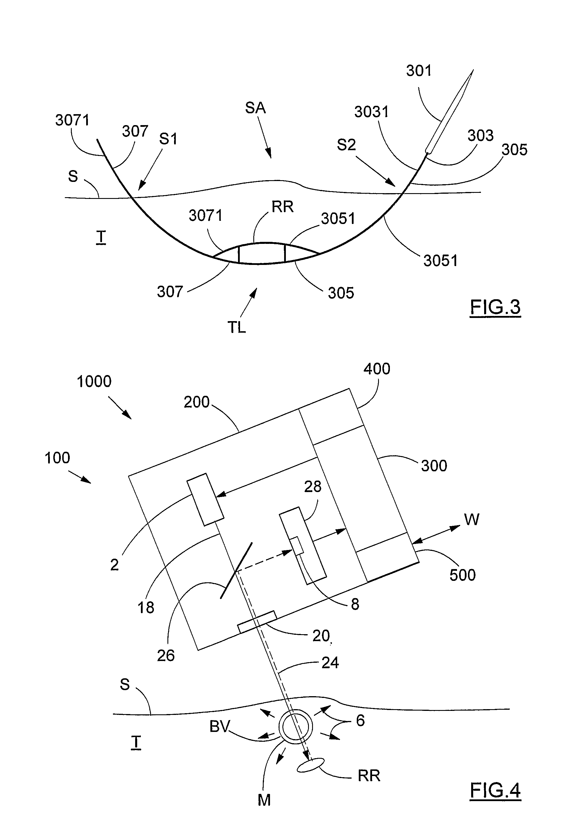
embodiment 1000
[0109]Another method of obtaining the glucose concentration of the blood B alone would be to synchronize spectral measurements with blood pulsation. If desired, spectral measurements taken by use of the embodiment 1000 are enhanced by synchronization of the data sampling in association with the rhythm of pulsation of the blood B. Since the blood volume in a blood vessel is higher during the high-pressure portion of the pulse rhythm than it is in the low-pressure phase, the difference between the absorption spectra obtained in the high-pressure portion of the pulse rhythm and the low-pressure phase thereof is the net result of absorption by the blood B alone.
[0110]For further enhancement, beams of radiation of different wavelength also improve detection accuracy.
[0111]If desired for calibration purposes, a single measurement is taken by conventional means from a sample of blood, for example by finger pricking. Once calibrated for a given user U, not shown in the Figs., net concentrat...
PUM
 Abstract
Description
Claims
Application Information