Open style head restraint with closeout and method for making same

a head restraint and open-style technology, applied in the field of head restraints, to achieve the effect of maximizing visibility and maximizing visibility

Inactive Publication Date: 2005-04-07
INTIER AUTOMOTIVE INC
View PDF10 Cites 6 Cited by
  • Summary
  • Abstract
  • Description
  • Claims
  • Application Information

AI Technical Summary

Benefits of technology

[0007] The invention is directed to an open style head restraint with a closeout and a method of making the head restraint. The closeout can be made of any desired material that maximizes visibility while preventing a portion of the occupant to become lodged in the halo during accident conditions. For example, the closeout can be made of a cellular type material that maximizes the visibility through the opening, such as a mesh, net, or the like. Preferably, the closeout is attached to the armature and / or the cross member to hold the closeout in place during manufacture of the head restraint. This can be accomplished by any means, such as attaching the closeout to armatures, posts, or the like. An advantage of using the cellular type material, such as the mesh, is that the material may become bonded to the foam filler during manufacture of the head restraint without the need of attaching the closeout to the armature and / or cross member during the manufacturing process. Other materials that can be used for the closeout include, but is not limited to, clear or semi-transparent plastic or plexiglass material. It should be noted that the closeout material also provides structural support for the head restraint and can absorb energy from the occupant during accident conditions.

Problems solved by technology

Another problem solved by the inventor is preventing the foam filler material from leaking onto the closeout during manufacture of the head restraint.

Method used


Image

  • Open style head restraint with closeout and method for making same
  • Open style head restraint with closeout and method for making same
  • Open style head restraint with closeout and method for making same

Examples


Embodiment Construction

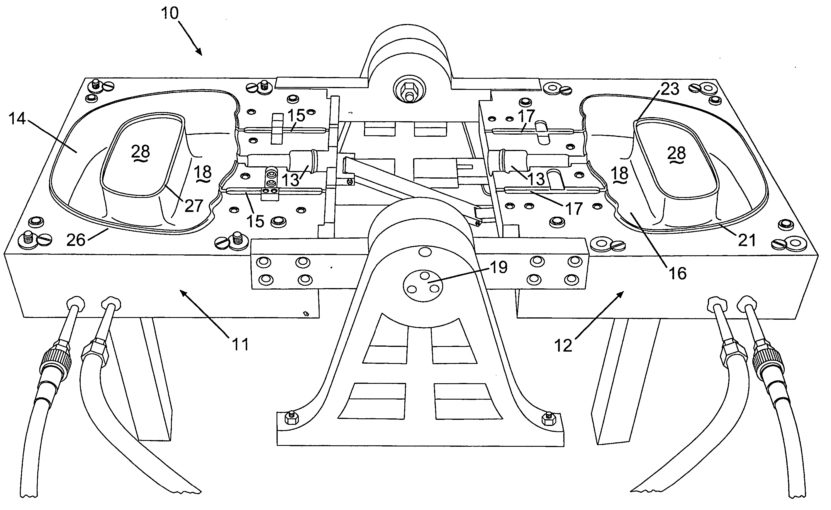
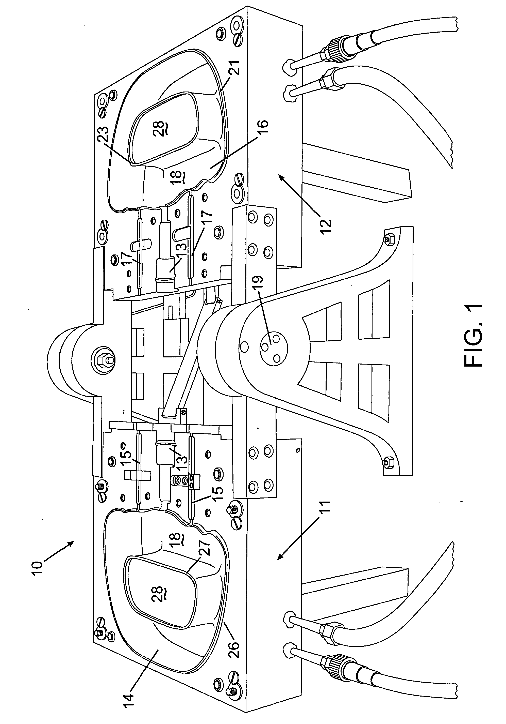
[0023] Referring to FIG. 1, the mold assembly 10 includes a first mold half 11 and a second mold half 12. The mold halves 11, 12 are movable relative to each other between an open position, as shown in FIGS. 1, 4-8 and 11, and a closed position, as shown in FIGS. 9 and 10. The first and second mold halves 11, 12 include first and second contoured mold surfaces 14, 16, respectively. The mold surfaces 14, 16 are concave and complimentary to each other such that the molded surfaces 14, 16 define a substantially enclosed mold cavity 18 when the mold assembly 10 is in the closed position. The surfaces of the mold surfaces 14, 16 defining the mold cavity 18 correspond to an outer contour of the head restraint (not shown in the Figures). The mold surfaces 14, 16 preferably include a textured surface that forms a final surface texture of the head restraint. It should be appreciated that while the mold surfaces 14, 16 are illustrated as concave, the mold surfaces 14, 16 may be of any suitabl...


PUM

PropertyMeasurementUnit
non-permeable aaaaaaaaaa
permeableaaaaaaaaaa
dimensionsaaaaaaaaaa

Abstract

An open style head restraint includes a closeout for providing structural integrity and safety. For providing maximum visibility, the closeout is preferably made of see-through material, for example, cellular material, such as mesh or net material, or non-cellular material, such as clear and semi-transparent plastic material, or the like. The open style head restraint is formed by affixing the closeout between the armatures and / or a top or bottom cross member. Next, a sealing material is applied between the closeout and the mold assembly to prevent the foam filler from seeping onto the closeout. Then, a release-mold coat, an in-coat, and a skin coat can be applied to the mold halves. Next, the closeout is properly positioned in the mold assembly and the armatures are secured. The foam filler is then injected while the mold assembly is in the closed position. Then, the foam filler is allowed to cure. After a sufficient period of time, the completed open style head restraint with closeout can be removed from the mold assembly.

Description

BACKGROUND OF THE INVENTION [0001] 1. Field of the Invention [0002] The invention is generally related to a head restraint, and in particular to an open style head restraint with a closeout for both aesthetic and / or structural purposes, and a method for making same. [0003] 2. Description of the Related Art [0004] Recent legislation has required vehicle seat head restraints to extend higher in vehicles for improved safety. For example, European legislation requires that the top of the head restraint be positioned 750 mm above the hip pivot point, which is substantially higher than most current designs. As a result of these tall seat designs, either the seat back is made taller and / or the head restraint is made taller. Because a taller seat back may obstruct the view of the occupant, it is preferred that the head restraint is made taller to maximize visibility. [0005] With a taller or larger head restraint design, the dimensions of the halo or opening may be sufficiently large that a ...

Claims


Application Information

Patent Timeline
Patent Type & Authority Applications(United States)
IPC IPC(8): A47C7/38B60N2/48
CPCB60N2/48A47C7/38B29C44/1271B60N2/80
Inventor INGWERSEN, KARSTEN
Owner INTIER AUTOMOTIVE INC
Why Eureka
Try Eureka