White light emitting device and white light source module using the same

a light emitting device and light source technology, applied in semiconductor devices, lighting and heating apparatus, instruments, etc., can solve the problems of color uniformity, increase the number of leds required, and higher circuit costs, so as to achieve superior color uniformity and high color reproducibility

Active Publication Date: 2008-06-05
SAMSUNG ELECTRONICS CO LTD
View PDF10 Cites 174 Cited by
  • Summary
  • Abstract
  • Description
  • Claims
  • Application Information

AI Technical Summary

Benefits of technology

[0010]An aspect of the present invention provides a white light emit...

Problems solved by technology

However, in the white light source module 10 described above, the R, G, and B LEDs 12, 14, and 16 are spaced apart from another, thereby potentially posing a problem to color uniformity.
This entails complicated circuit configuration for driving and controlling the LED of ...

Method used


Image

  • White light emitting device and white light source module using the same
  • White light emitting device and white light source module using the same
  • White light emitting device and white light source module using the same

Examples


Embodiment Construction

[0031]Exemplary embodiments of the present invention will now be described in detail with reference to the accompanying drawings. This invention may, however, be embodied in many different forms and should not be construed as limited to the embodiments set forth herein. Rather, these embodiments are provided so that this disclosure will be thorough and complete, and will fully convey the scope of the invention to those skilled in the art. In the drawings, the shapes and dimensions may be exaggerated for clarity, and the same reference signs are used to designate the same or similar components throughout.

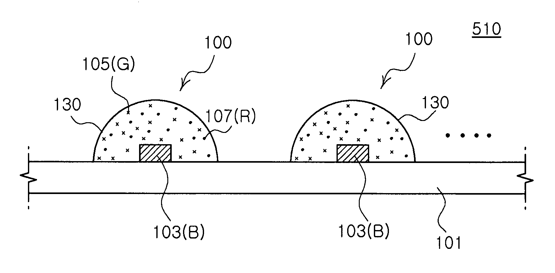
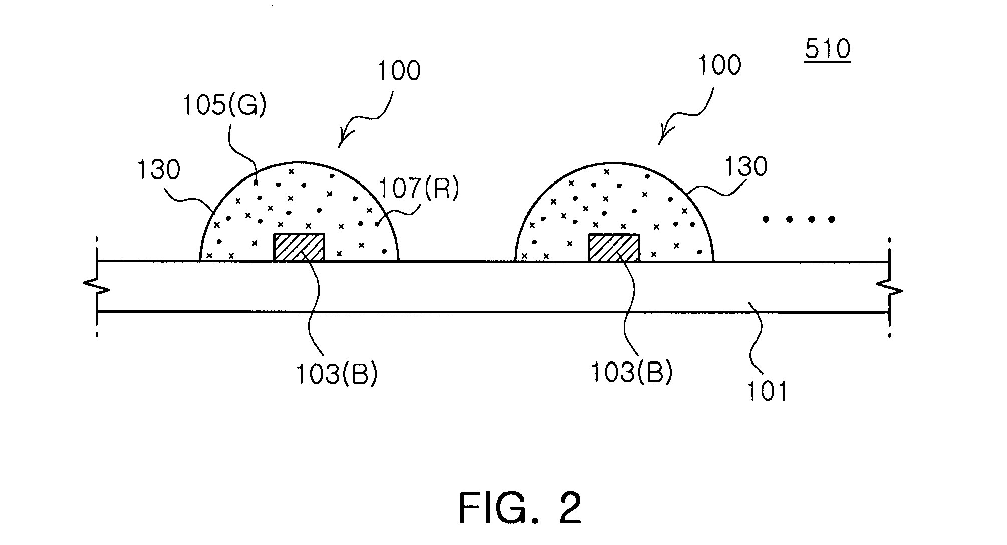
[0032]FIG. 2 is a schematic cross-sectional view illustrating a white light emitting device and a white light source module using the same according to an exemplary embodiment of the invention. Referring to FIG. 2, the white light source module 510 includes a circuit board 101 such as a printed circuit board, and at least one white light emitting device 100 disposed on the circuit bo...


PUM

PropertyMeasurementUnit
Widthaaaaaaaaaa
Widthaaaaaaaaaa
Widthaaaaaaaaaa

Abstract

A white light emitting device including: a blue light emitting diode chip having a dominant wavelength of 443 to 455 nm; a red phosphor disposed around the blue light emitting diode chip, the red phosphor excited by the blue light emitting diode chip to emit red light; and a green phosphor disposed around the blue light emitting diode chip, the green phosphor excited by the blue light emitting diode chip to emit green light, wherein the red light emitted from the red phosphor has a color coordinate falling within a space defined by four coordinate points (0.5448, 0.4544), (0.7079, 0.2920), (0.6427, 0.2905) and (0.4794, 0.4633) based on the CIE 1931 chromaticity diagram, and the green light emitted from the green phosphor has a color coordinate falling within a space defined by four coordinate points (0.1270, 0.8037), (0.4117, 0.5861), (0.4197, 0.5316) and (0.2555, 0.5030) based on the CIE 1931 color chromaticity diagram.

Description

CROSS-REFERENCE TO RELATED APPLICATIONS[0001]This application claims the priority of Korean Patent Application Nos. 2006-122631 filed on Dec. 5, 2007 and 2007-12112 filed on Feb. 6, 2007, in the Korean Intellectual Property Office, the disclosure of which is incorporated herein by reference.BACKGROUND OF THE INVENTION[0002]1. Field of the Invention[0003]The present invention relates to a white light emitting device and a white light source module using the same, and more particularly, to a white light emitting device beneficially applicable to a backlight unit of a liquid crystal display to ensure high color reproducibility, and a white light source module using the same.[0004]2. Description of the Related Art[0005]Recently, a light emitting diode (LED) is highlighted as a light source of a backlight unit (BLU) employed in liquid crystal displays such as lap top computers, monitors, mobile phones and TVs. A cold cathode fluorescent lamp (CCFL) has been in use as a white light source...

Claims


Application Information

Patent Timeline
IPC IPC(8): H01L33/00H01L33/32H01L33/50H01L33/56H01L33/60H01L33/62
CPCC09K11/0883C09K11/7731C09K11/7734F21K9/00H05B33/12G02F1/133609H01L33/504Y02B20/181G02F1/133603Y02B20/00C09K11/77347C09K11/77348A43B13/145A43B13/182A43B13/04A43B13/12
Inventor YOO, CHUL HEEYEONG, YOUNG JUNEPARK, YOUNG SAMHAN, SEONG YEONKIM, HO YEONHAHM, HUN JOOKIM, HYUNG SUK
Owner SAMSUNG ELECTRONICS CO LTD
Why Eureka
Try Eureka