Water pipe end structure and connection therefor

Inactive Publication Date: 2008-06-05
MIRAI KOGYO KK
View PDF16 Cites 12 Cited by
  • Summary
  • Abstract
  • Description
  • Claims
  • Application Information

AI Technical Summary

Benefits of technology

[0023]The present invention further provides an inner piece as described below. The inner piece is used to connect a pipe main body of a water pipe made of a synthetic resin to a connector so as to prevent the pipe main body from slipping out of the connector. The inner piece is made of metal and is annular. The inner piece is inserted into an end of the pipe main body. The inner piece has its diameter increased from the inside of the pipe main body so as to form a radially outward swollen portion in a part of that portion of the pipe main body which corresponds to the inner piece, the swollen portion engaging with the connector.
[0024]The present invention further provides a formation member as described below. The formation member is used to connect a pipe main body of a wa

Problems solved by technology

Thus, the operation of forming the flange portion 1101b is very complicated.
Thus, an unnecessarily heavy load is imposed on the end of t

Method used


Image

  • Water pipe end structure and connection therefor
  • Water pipe end structure and connection therefor
  • Water pipe end structure and connection therefor

Examples


first embodiment

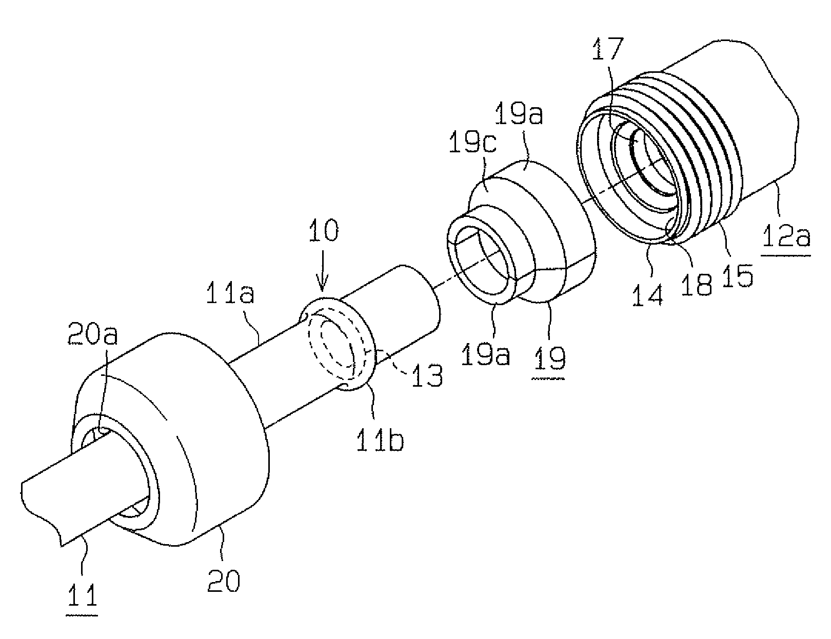
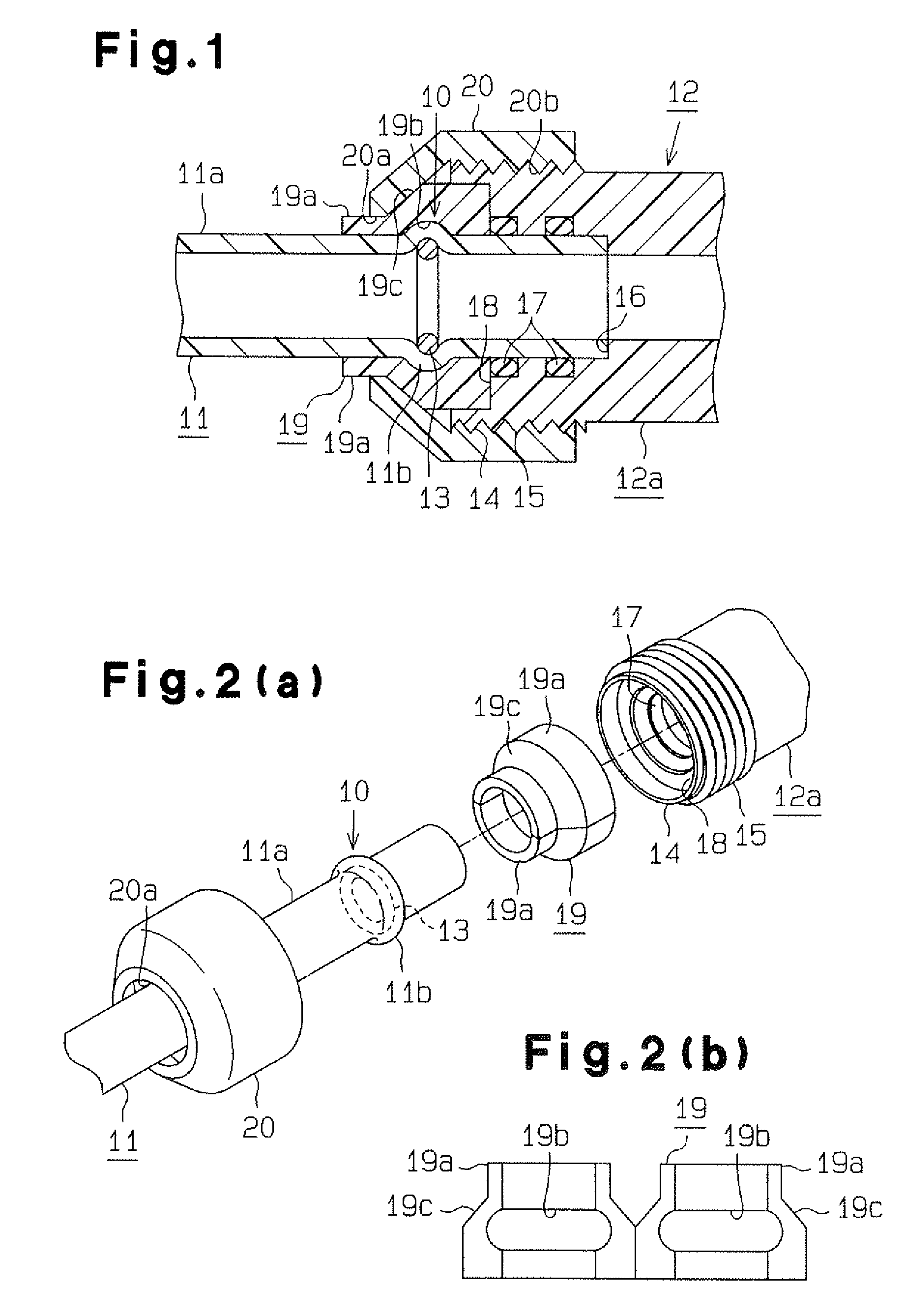
[0076]With reference to FIGS. 1 to 5, description will be given below of a first embodiment that embodies the present invention. The terms “upward”, “downward”, “right”, and “left” in the description below of the present embodiment correspond to the upper, lower, right, and left sides, respectively, of the drawings.

[0077]As shown in FIG. 1, an end structure 10 of a water pipe 11 is formed at the right end of a pipe main body 11a of the water pipe 11 in order to connect, in a lockable manner, the water pipe 11, made of a synthetic resin, to a joint 12 operating as a connector.

[0078]The end structure 10 comprises a swollen portion 11b provided at the right end of the pipe main body 11a and projected outside by increasing the diameter of a ring piece 13 from the inside of the ring piece 13; the ring piece 13 is inserted into the right end of the pipe main body 11a and operates as an inner piece. The ring member 13 is formed of for example, copper. The ring member 13 may be formed of me...

second embodiment

[0109]the present invention will be described below with reference to FIGS. 6 to 8. In the present embodiment, only the configurations of the end structure 10 and joint 12 in the embodiments shown in FIGS. 1 to 5 are changed. Accordingly, the detailed description of similar components is omitted. Also in the present embodiment, the terms “upward”, “downward”, “right”, and “left” in the description below correspond to the upper, lower, right, and left sides, respectively, of the drawings.

[0110]As shown in FIG. 6, in the end structure 10 of the water pipe 11, an inner sleeve 25 made of metal and operating as an inner piece is fitted into the pipe main body 11a between the swollen portion 11b of the pipe main body 11a and the opening in the pipe main body 11a. The inner sleeve 25 may be formed of a synthetic resin. The inner sleeve 25 comprises a cylindrical inner portion 25a and an engagement flange portion 25b formed at the right end of the inner portion 25a so as to project radially...

third embodiment

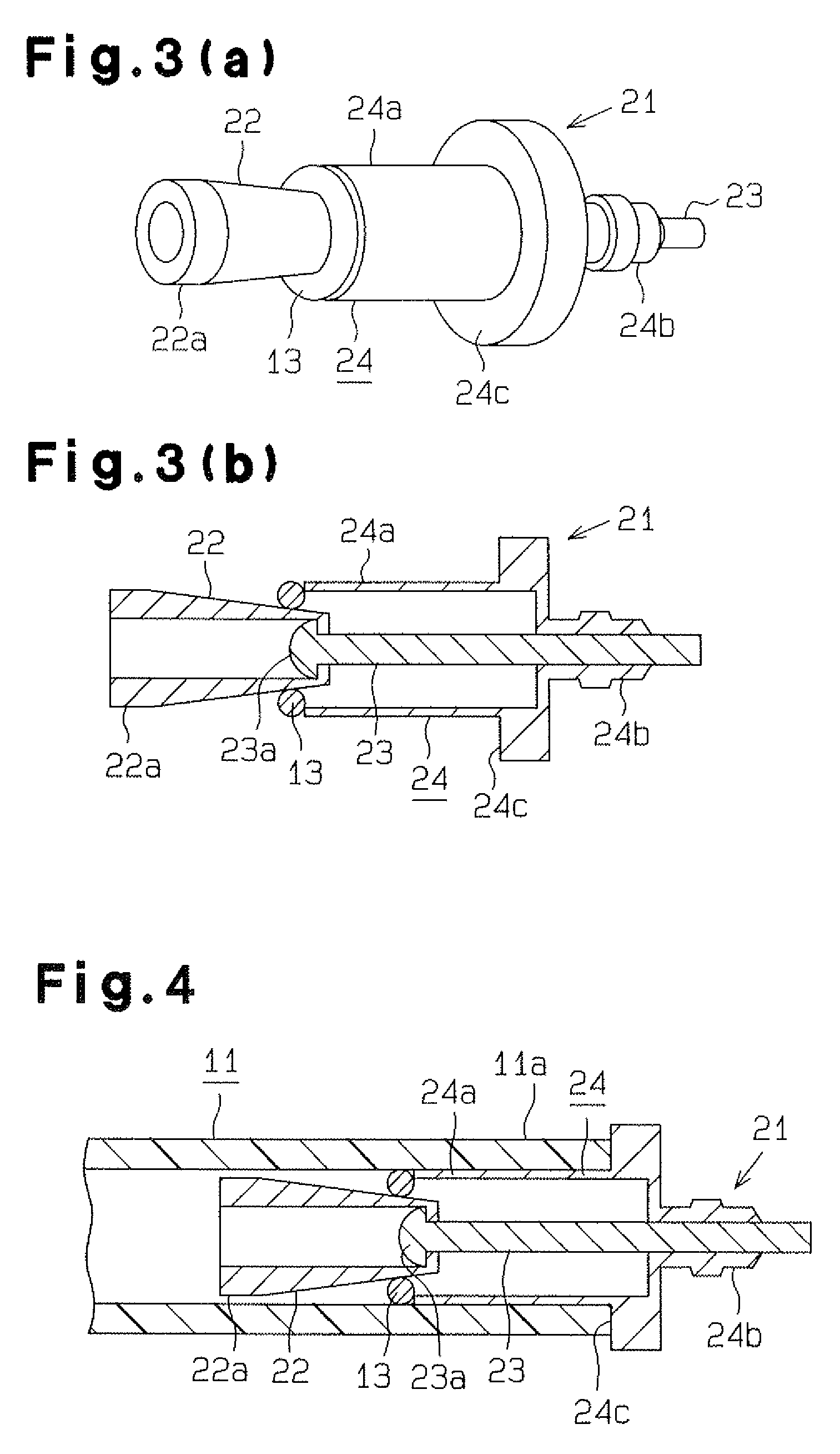
[0120]the present invention will be described below with reference to FIGS. 9 to 13. In the present embodiment, only the configurations of the end structure 10, ring piece 13, and joint 12 in the embodiments shown in FIGS. 1 to 5 are changed. Accordingly, the detailed description of similar components is omitted. Also in the present embodiment, the terms “upward”, “downward”, “right”, and “left” in the description below correspond to the upper, lower, right, and left sides, respectively, of the drawings.

[0121]As shown in FIG. 9, the end structure 10 of the water pipe 11 comprises the swollen portion 11b formed by increasing the diameter of a cylinder 34 from its inside to swell the end of the pipe main body 11a radially outward; the cylinder 34 is inserted into the right end of the pipe main body 11a and operates as an inner piece. The cylinder 34 is formed of metal and has an outer diameter before enlargement slightly smaller than the inner diameter of the pipe main body 11a (see F...


PUM

PropertyMeasurementUnit
Diameteraaaaaaaaaa

Abstract

A water pipe includes a pipe main body made of a synthetic resin and an annular metal inner piece inserted into an end of the pipe main body. The inner piece has its diameter increased from the inside of the pipe main body so as to increase the diameter of at least a part of that portion of the pipe main body which corresponds to the inner piece. The inner diameter of the inner piece the diameter of which has been increased is almost the same as that of a portion of the pipe main body which is not enlarged by the inner piece.

Description

FIELD OF THE INVENTION[0001]The present invention relates to an end structure of a water pipe made of a synthetic resin and used as a hot water supply pipe, a water supply pipe, or the like, as well as a water pipe comprising the end structure. The present invention also relates to a structure connecting a water pipe and a connector together and a method of forming an end structure of a water pipe.BACKGROUND OF THE INVENTION[0002]As shown in FIG. 45, for example, Japanese Laid-Open Patent Publication No. 7-42883 discloses a water pipe 1101 made of a synthetic resin and used as a water supply pipe. The water pipe 1101 comprises an end structure connected to a cylindrical joint 1102 in a lockable manner.[0003]A pipe main body 1101a of the water pipe 1101 has a flange portion 1101b formed at its end and projecting outward from an outer peripheral surface of the pipe main body 1101a along a circumferential direction of the pipe main body 1101a. Connecting cylindrical portions 1103 are f...

Claims


Application Information

Patent Timeline
IPC IPC(8): F16L47/00
CPCF16L13/146F16L13/147F16L19/0231F16L37/144F16L19/0286F16L23/024F16L19/0283
Inventor SHIMIZU, SHOHACHI
Owner MIRAI KOGYO KK
Why Eureka
Try Eureka