Ultrasonic flow meter system

a flow meter and ultrasonic technology, applied in the direction of volume/mass flow measurement, measurement devices, instruments, etc., can solve the problems of adding to the cost and complexity of the flow meter, affecting the accuracy of the mean flow rate, and the flow rate dependent or empirical profile correction factors are often invalid, so as to achieve the effect of adding significant cost or complexity and accurately determining the mean flow ra

Active Publication Date: 2008-07-03
BAKER HUGHES INC
View PDF16 Cites 29 Cited by
  • Summary
  • Abstract
  • Description
  • Claims
  • Application Information

AI Technical Summary

Benefits of technology

[0008]Embodiments of this invention provide a flow meter capable of detecting the mean flow rate with accuracy using less than four transducer pairs. The transducers employed may be standard lower cost wetted transducers, although the invention is not so limited. Also, various embodiments e

Problems solved by technology

However, the analytical or empirical profile correction factors are often flow rate dependent and invalid if the flow profile is not symmetrical, accuracy is thus comprised.
Also, if the fluid properties are unknown, or if the conditions upstream of the transducers are complex, a severely distorted flow profile can result.
Each additional path through the flow requires an additional transducer pair, typically adding to the cost and complexity of the flow meter.
Also, a high number of

Method used


Image

  • Ultrasonic flow meter system
  • Ultrasonic flow meter system
  • Ultrasonic flow meter system

Examples


Embodiment Construction

[0027]Aside from the embodiments disclosed below, this invention is capable of other embodiments and of being practiced or being carried out in various ways. Thus, it is to be understood that the invention is not limited in its application to the details of construction and the arrangements of components set forth in the following description or illustrated in the drawings. The claims hereof are not to be limited to the embodiments described herein. Moreover, the claims hereof are not to be read restrictively unless there is clear and convincing evidence manifesting a certain exclusion, restriction, or disclaimer.

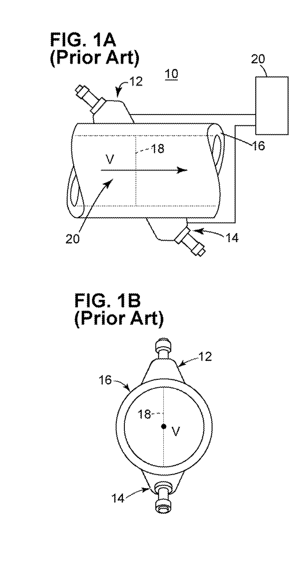
[0028]One typical prior art flow meter 10, FIG. 1A includes a transducer pair 12, 14 with upstream ultrasonic transducer 12 and downstream ultrasonic transducer 14. Ultrasonic transducers 12 and 14 may be clamp on transducers, or wetted transducers, placed on opposite sides of conduit 16, or the transducers may be on the same side of conduit 16 (not shown). Transducer 12 se...


PUM


Abstract

An ultrasonic flow meter system includes transducers arranged with respect to a conduit to define at least one chordal path through fluid flowing in the conduit, and at least one transmitting transducer and receiving transducer pair on the chordal path for generating a transit time signal. At least one receiving transducer is positioned to receive scattered energy to generate a range gated Doppler signal. The system further includes a processing subsystem for exciting the at least one transmitting transducer. The processing subsystem is responsive to the transit time signal and the range gated Doppler signal and configured to generate a velocity profile and a mean velocity of the fluid in the conduit.

Description

FIELD OF THE INVENTION[0001]This subject invention relates to ultrasonic flow meter technology.BACKGROUND OF THE INVENTION[0002]Ultrasonic transducers are used to measure the flow rate of a flow in a conduit. Transit time flow metering is a common ultrasonic method to measure the mean pipe flow rate. One transducer, when excited or energized by an electronic controller, emits a sound wave through the flow which is detected by another transducer. The controller alternates between the receiver and transmitter back and forth to receive signals traveling along and against the direction of flow. The transit times of the wave are then used to calculate speed of sound of the fluid and further calculate the flow rate by using the speed of sound, path length, the transit times, and conduit dimension data.[0003]The flow velocity has a radial distribution described by its flow profile, which is a function of the Reynolds number for the flow medium, pipe roughness, and the conduit configuration...

Claims


Application Information

Patent Timeline
IPC IPC(8): G01F1/66
CPCG01F1/668G01F1/663
Inventor AO, XIAOLEI SHIRLEYUMINA, JOHN ALBERTFURLONG, EDWARD R.
Owner BAKER HUGHES INC
Why Eureka
Try Eureka