Common-mode filter device and system

A common-mode filter and source filter technology, applied in output power conversion devices, inductors, broadband transformers, etc., can solve the problems of increasing installation costs and reducing power conversion efficiency of transformers, and achieve the effect of reducing costs.

Active Publication Date: 2013-12-25
KERRYJ INVESTMENT
View PDF4 Cites 15 Cited by
  • Summary
  • Abstract
  • Description
  • Claims
  • Application Information

AI Technical Summary

Problems solved by technology

Transformers reduce power conversion efficiency and increase installed cost, size and mass

Method used


Image

  • Common-mode filter device and system
  • Common-mode filter device and system
  • Common-mode filter device and system

Examples


Embodiment Construction

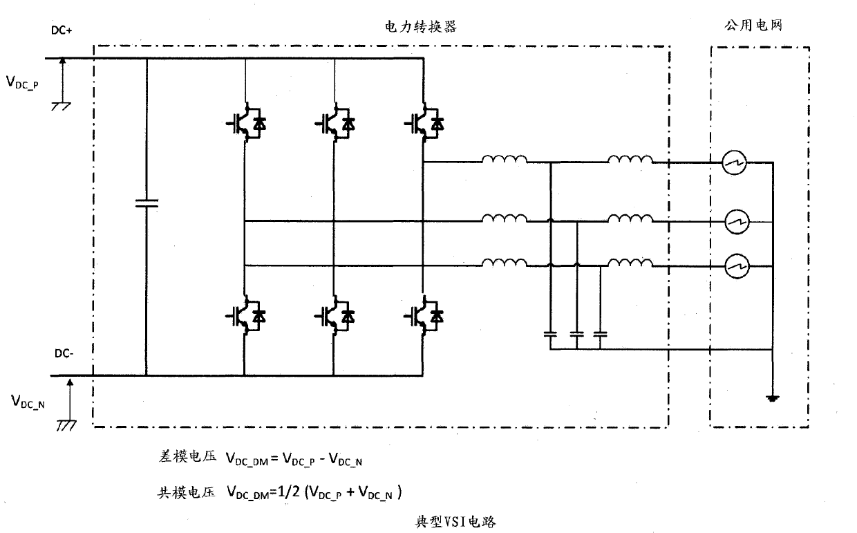
[0092] Reference Figure 4 The block diagram and partial circuit diagram shown, which show the common mode filter device and system in an exemplary circuit. The device can use active common mode filters or passive common mode filters. The power converter is shown with an AC power port connected to the AC utility grid and a DC power port connected to the input port of the active CM filter. The output port of the active CM filter is connected to an external circuit, such as a power supply or load.

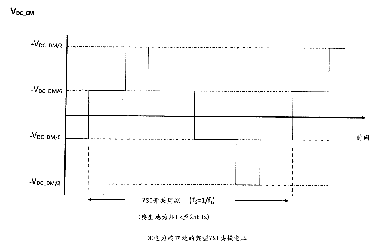
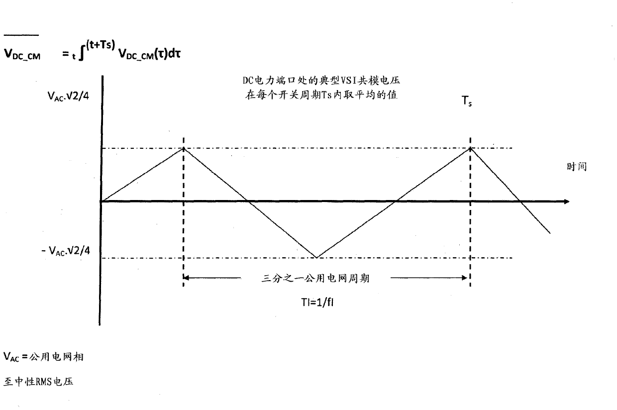
[0093] In this form, the common mode filter device and system has a common mode filter used in series with the power converter to support the common mode voltage difference between the power converter ports and control the common mode current to an acceptable level. The power converter may be a VSI. The common-mode filter uses the real-time measured common-mode current, and uses the common-mode current return path and impedance to provide real-time control of the common-mode current. ...


PUM


Abstract

A common-mode filter device and system for regulating aspects of power conversion by a power converter from external source such as solar panels to another external circuit wherein the common-mode filter device substantially attenuates common-mode voltage at the switching frequency plus harmonics of the power converter. The power converter can be single phase, but is preferably a multiple phase.

Description

Technical field [0001] The present invention relates to a device and system for a power converter and inverter system using an active common mode filter. Specifically, the present invention relates to a common mode filter device and system for adjusting various aspects of power conversion from an external source such as a solar panel to a public grid, but the present invention is not limited thereto. Background technique [0002] Power converters are used to transfer power between circuits. Each circuit is connected to a different power port of the power converter. Each power port has at least two power conductors. The power port voltage is characterized by differential mode (DM) voltage and common mode (CM) voltage. DM voltage is the potential difference between the pair of power conductors. The CM voltage is the average potential difference between all power conductors and a reference potential such as ground (earth). Similarly, the power port current is characterized by D...

Claims


Application Information

Patent Timeline
Patent Type & Authority Applications(China)
IPC IPC(8): H02M1/12H02M1/14H02J3/01H03H11/00
CPCH01F19/06H01F27/25H01F2017/0093H02M1/12H03H7/427H02M1/123
Inventor 西蒙·罗伯特·沃尔
Owner KERRYJ INVESTMENT
Why Eureka
Try Eureka