
Mobile power box

A mobile power and box technology, applied in the field of electric power, can solve the problems of inability to move, cannot be moved, and the mobile power box cannot meet the application, and achieves the effect of a large range of use

Inactive Publication Date: 2010-09-01
JIANGYIN YIDA ELECTRICAL APPLIANCE
View PDF6 Cites 3 Cited by
  • Summary
  • Abstract
  • Description
  • Claims
  • Application Information

AI Technical Summary

Problems solved by technology

[0002] At present, the mobile power boxes seen on the market are not mobile power boxes in the true sense, and they cannot be moved when the user supplies power. For example, a mobile power box disclosed in patent 200910014512.2 needs to be moved before use, and then Use wires to connect the wire plug button and the incoming wire terminal button to form a path to realize power supply. However, it cannot be moved during use. When the power box needs to be moved during use, it can only be powered off first. Disconnect the wire between the wire plug button and the incoming wire terminal button, then move the power box to the required position, then connect the wire plug button and the incoming wire terminal button with a wire, and finally power on and use it, so it cannot be called A mobile power box in the true sense, especially in occasions that require real-time uninterrupted power supply, the mobile power box cannot meet the application

Method used


Image

  • Mobile power box
  • Mobile power box
  • Mobile power box

Examples


Embodiment Construction

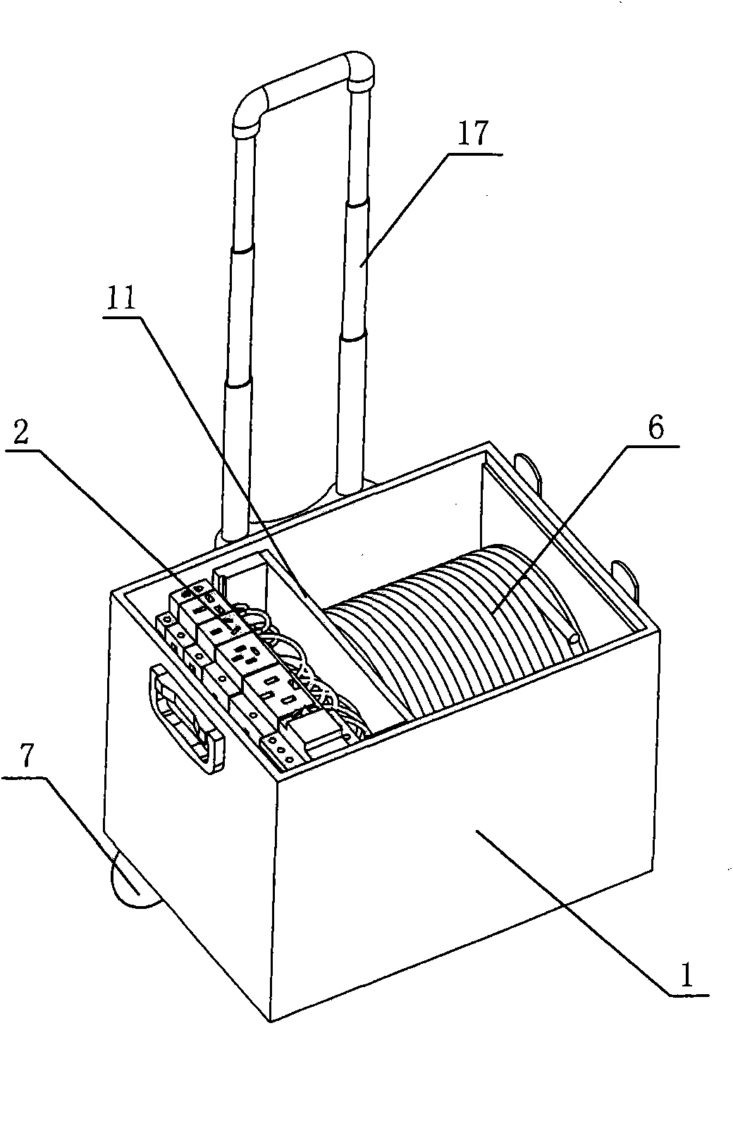
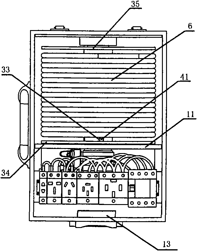
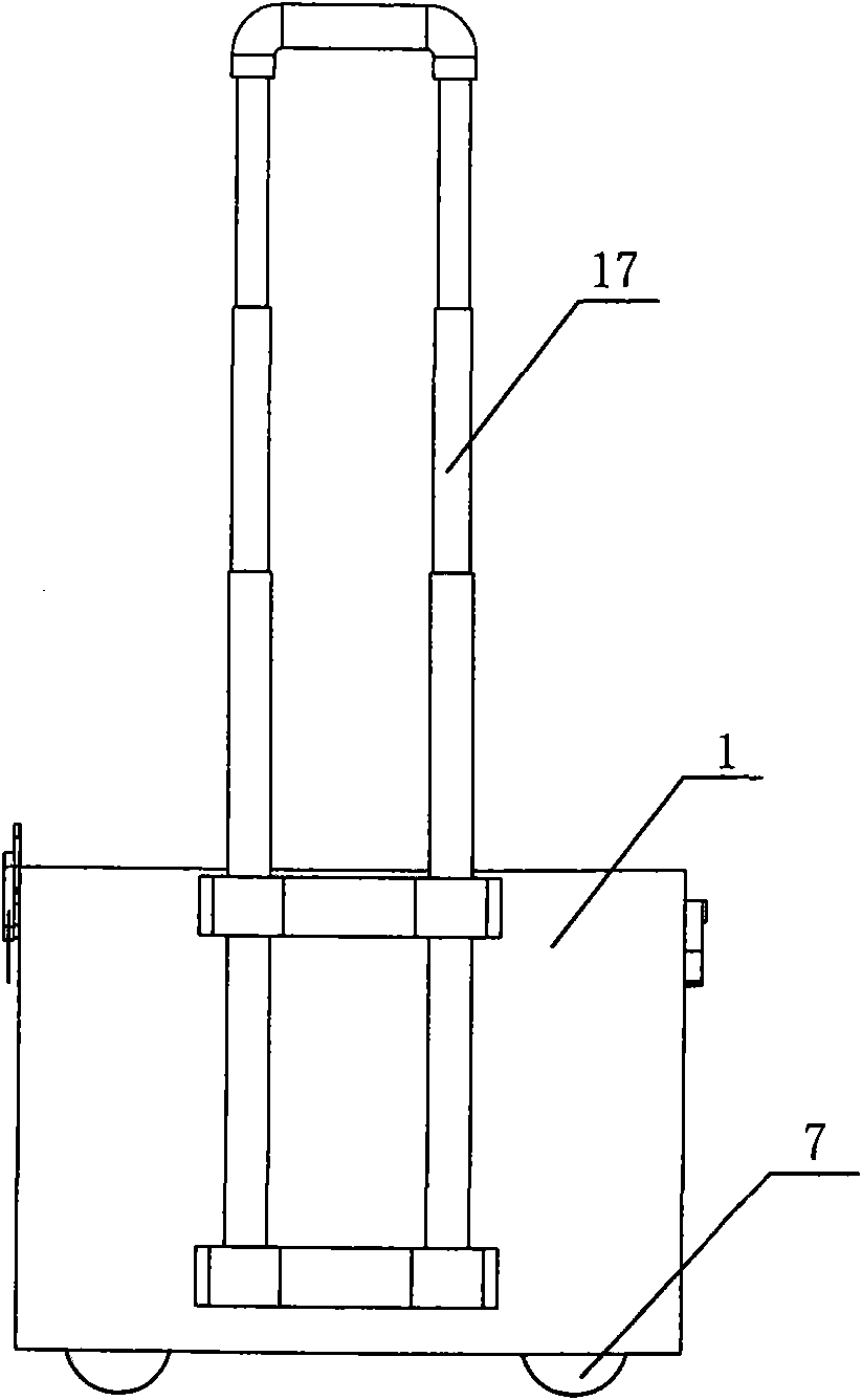
[0028] see Figure 1-5 , the present invention relates to a mobile power supply box, comprising a box body 1, a control panel 2 is arranged inside the box body 1, a switch 21, an overload protector 22 and a socket 23 are arranged on the control panel 2, and the switch 21. The overload protector 22 and the socket 23 are connected in series. The power box 1 is provided with a partition 11 to divide the box into two parts. The partition 11 has a through hole through which a rotating shaft 3 passes. Through holes and relatively rotatably installed in the box body 1, one end of the rotating shaft 3 is provided with a perforated shaft 31, and the other end is provided with a rotating support shaft 32, and the end of the rotating shaft 3 close to the perforated shaft 31 is wound with an electric wire 6. 3 There are several wiring slots 33 on one end close to the rotating support shaft 32, and the conductive slip rings 4 corresponding to the number of wiring slots 33 are sleeved on th...


PUM


Abstract

The invention relates to a mobile power box. The power box comprises a box body(1), wherein a baffle plate(11) is arranged in the box body(1) and provided with a through hole, a rotary shaft(3) passes the through hole and is arranged in the box body(1) in a relative rotation manner, one end of the rotary shaft(3) is provided with a through hole shaft(31), and the other end of the rotary shaft(3) is provided with a rotary support shaft(32); the end, close to the through hole shaft(31), of the rotary shaft(3) is wound with a wire(6), and the end, close to the rotary support shaft(32), of the rotary shaft(3) is provided with a plurality of wire grooves(33) and is also sleeved with electrically conductive slip rings(4) which correspond to the wire grooves(33) in number; the slip rings(4) are led out by the wire grooves(33) in an electric terminal(41); and, a carbon brush base(5) corresponding to the electrically conductive slip rings(4) is arranged between the side walls of the baffle plate(11) and the box body(1). The mobile power box can move at any time and realize uninterrupted power supply.

Description

(1) Technical field [0001] The invention relates to a power supply box, in particular to a mobile power supply box, and belongs to the technical field of electric power. (2) Background technology [0002] At present, the mobile power boxes seen on the market are not mobile power boxes in the true sense, and they cannot be moved when the user supplies power. For example, a mobile power box disclosed in patent 200910014512.2 needs to be moved before use, and then Use wires to connect the wire plug button and the incoming wire terminal button to form a path to realize power supply. However, it cannot be moved during use. When the power box needs to be moved during use, it can only be powered off first. Disconnect the wire between the wire plug button and the incoming wire terminal button, then move the power box to the required position, then connect the wire plug button and the incoming wire terminal button with a wire, and finally power on and use it, so it cannot be called ...

Claims


Application Information

Patent Timeline
Patent Type & Authority Applications(China)
IPC IPC(8): H01R13/46H01R13/72H01R13/70H01R39/64
Inventor 张旦芬
Owner JIANGYIN YIDA ELECTRICAL APPLIANCE
Learn More