Projector mount

a projector and mounting bracket technology, applied in the field of projector mounting brackets, can solve the problems of large and unwieldy installation of conventional projector mounting brackets, inconvenient positioning of media projectors on tables or similar surfaces, and insufficient ceiling suppor

Inactive Publication Date: 2008-07-31
PEERLESS INDS
View PDF13 Cites 39 Cited by
  • Summary
  • Abstract
  • Description
  • Claims
  • Application Information

AI Technical Summary

Benefits of technology

[0006]Various embodiments of the present invention provide a projector mount for use with a variety of devices, especially media projectors. A media projector is operatively connected to a connection block, for example, via an adapter, where the connection block is then engaged with a projector mount body. The projector mount body in turn can be flush mounted to a ceiling or similar support structure. Alternatively, the projector mount body can be attached to an extension column at a first end, where a second end of the extension column is attached to the ceiling or similar support structure. The projector mount enables images of a media projector to be sufficiently aligned with a projection screen upon which the images are to be displayed. The alignment of the projector mount is achieved through pitch and roll adjustment mechanisms incorporated into the projector mount utilizing worm gears working in conjunction with worms. Use of the worm gears provides easy yet secure adjustment of the projector mount. Alternatively, lead screws can be used in place of the worms to effectuate the same adjustment mechanisms. Alignment of the projector mount with regard to yaw to achieved by manually rotating the projector mount.

Problems solved by technology

Because the required distance could put the media projector behind viewers situated in front of the projection screen, it was a common occurrence for a viewer to inadvertently block the display being projected from the media projector.
Therefore, positioning a media projector on a table or similar surface was undesirable.
However, conventional projector mounts are often large and unwieldy to install, require ample ceiling support, and are visually unappealing.
Furthermore, the plurality of fasteners tended to easily slip or move out of alignment when adjusting the conventional projector mounts.
In addition, conventional projector mounts do not provide an easy and convenient system and method of making necessary adjustments to enable the display being cast to be satisfactorily aligned with the projector screen.

Method used


Image

  • Projector mount
  • Projector mount
  • Projector mount

Examples


Embodiment Construction

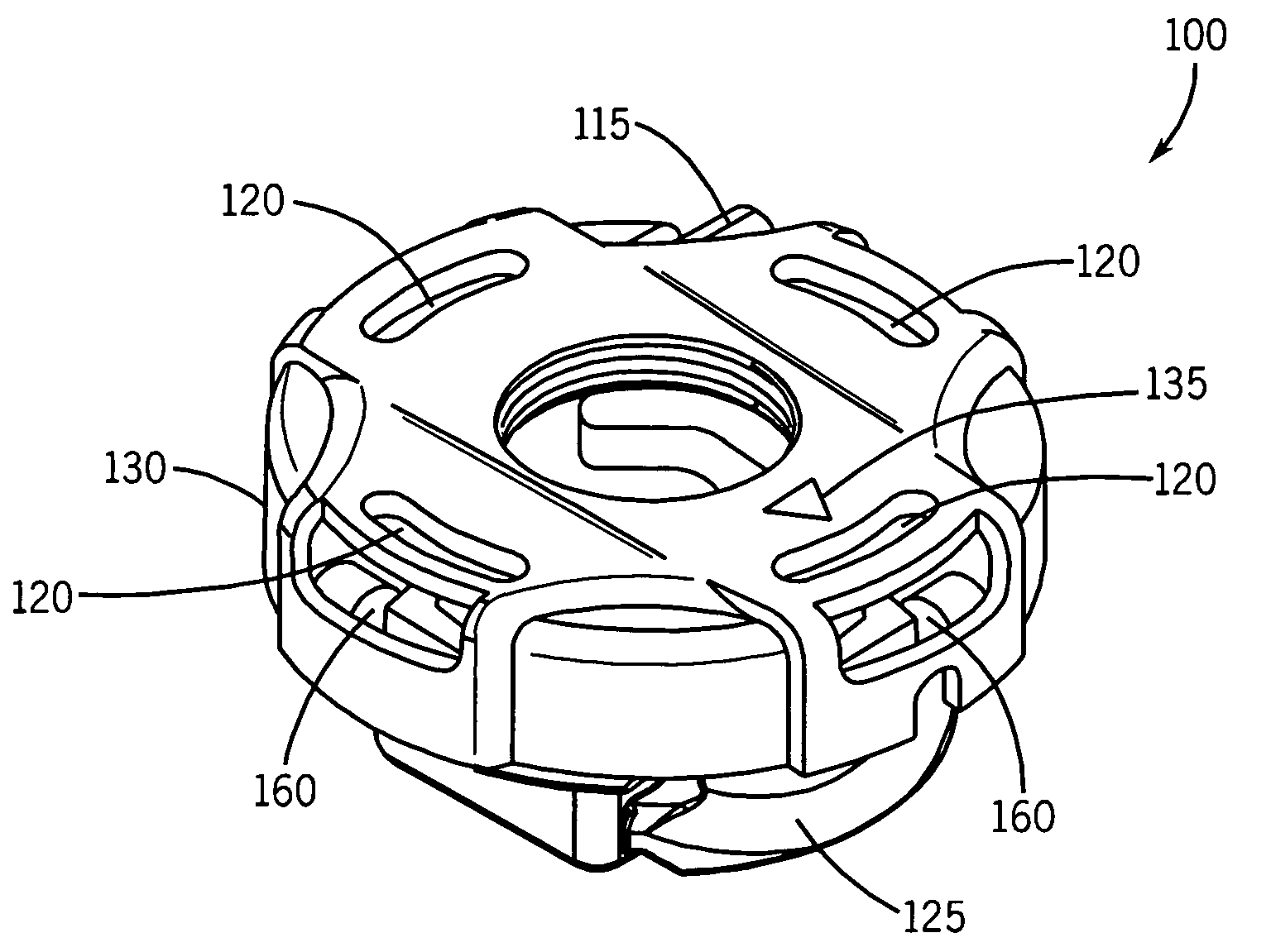
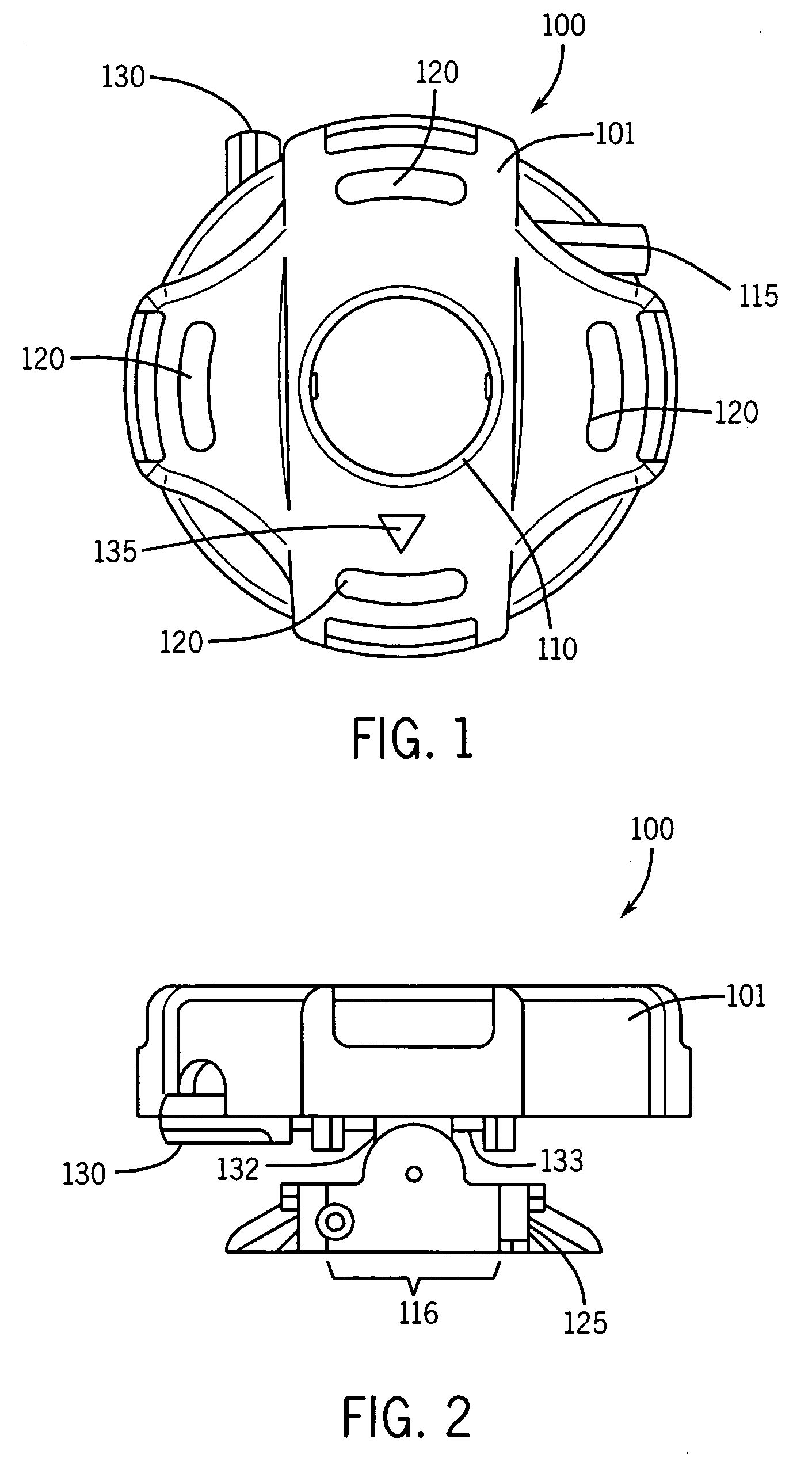
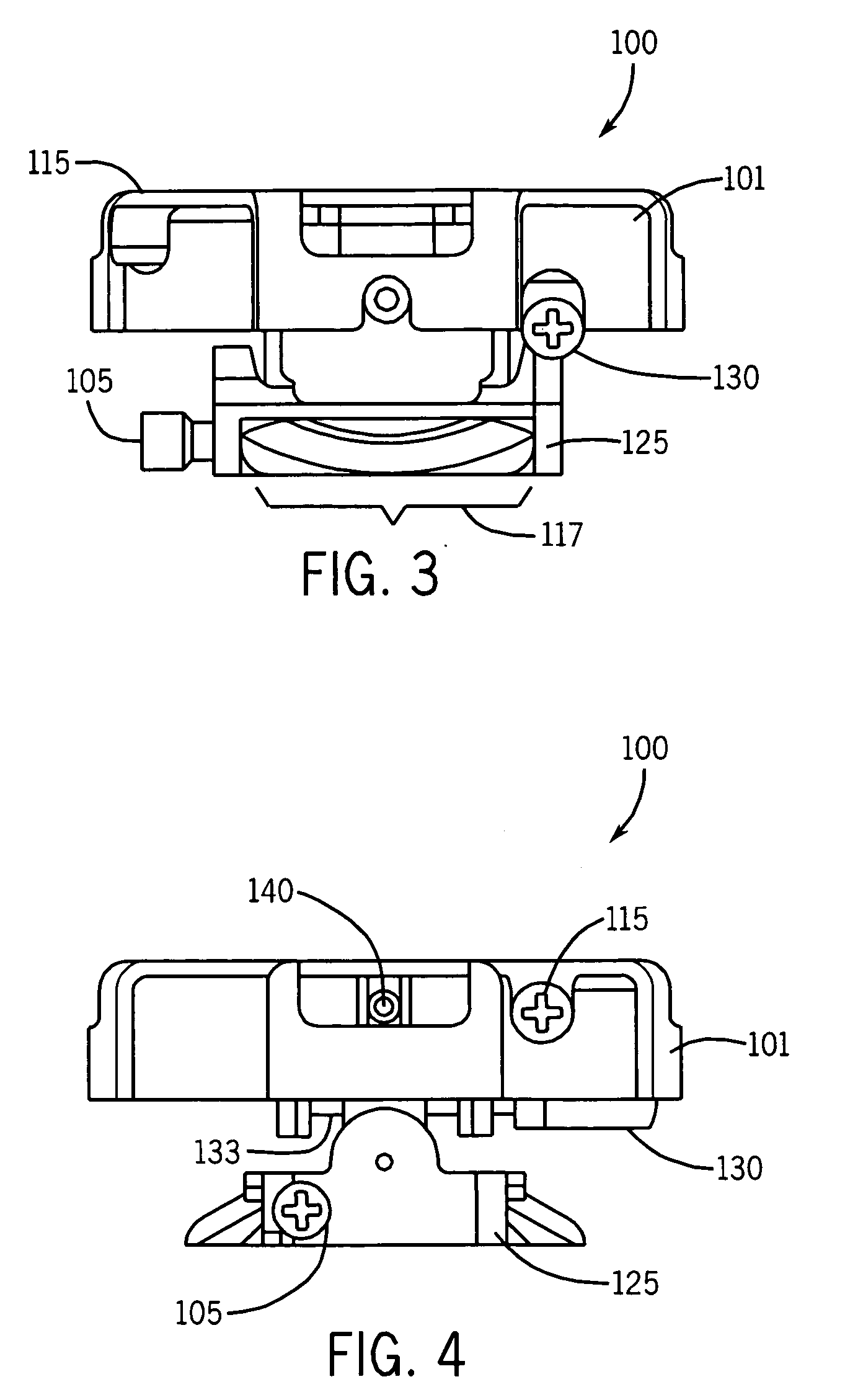
[0023]The various embodiments of the present invention provide a projector mount in which a media projector can be conveniently and easily mounted. The projector mount can be adjusted via a plurality of adjustment knobs driven by worms working in conjunction with worm gears, thus affecting an orientation of the media projector and an image or display projected from the media projector in a variety of directions with regard to yaw, pitch, and roll. Alternatively, lead screws can be utilized in place of the worms. In addition to easily adjusting the orientation of the projector mount, the projector mount only be adjusted via the plurality of adjustment knobs. For example, manually moving the media projector or the projector mount without utilizing the adjustment knobs is not possible. Because the adjustment of the media projector orientation within the projector mount can only be achieved using the plurality of adjustment knobs in conjunction with the worm gears, the orientation is mo...


PUM


Abstract

A low profile projector mount for media projectors, enabling images of a media projector to be sufficiently aligned with a projection screen upon which the images are to be displayed. The alignment of the low profile projector mount is achieved through pitch, roll, and/or yaw adjustment mechanisms incorporated into the low profile projector mount. The low profile projector mount can be flush mounted to a ceiling or attached to an extension column or other intermediary support system. A quick-release system allows a projector attached to the low profile, projector mount to be removed without disturbing the low profile, projector mount. In addition, retractable members for effectuating the pitch, roll, and/or yaw adjustments are utilized.

Description

CROSS-REFERENCE TO RELATED APPLICATIONS[0001]The present application claims priority to U.S. Provisional Patent Application No. 60 / 881,807, filed Jan. 19, 2007.FIELD OF THE INVENTION[0002]The present invention relates generally to mounting systems. More particularly, the present invention relates to mounting systems for use with devices such as media projectors.BACKGROUND OF THE INVENTION[0003]This section is intended to provide a background or context to the invention that is recited in the claims. The description herein may include concepts that could be pursued, but are not necessarily ones that have been previously conceived or pursued. Therefore, unless otherwise indicated herein, what is described in this section is not prior art to the description and claims in this application and is not admitted to be prior art by inclusion in this section.[0004]Display devices such as media projectors offer an alternative to traditional cathode ray tube (CRT) televisions and monitors, and ...

Claims


Application Information

Patent Timeline
Patent Type & Authority Applications(United States)
IPC IPC(8): F16M11/00A47G29/00
CPCF16M11/10F16M11/12F16M13/027F16M11/2071F16M11/18
Inventor WHITLEY, ANDYLAM, DERRIKBOSCH, MARCUS WILLI KARL GERHARD
Owner PEERLESS INDS
Why Eureka
Try Eureka