Objective lens actuator and optical pickup device having the same

a technology of actuator and optical pickup, which is applied in the manufacture of optical heads, instruments, data recording, etc., can solve the problems of degrading the quality of affecting the quality of the information read by the optical pickup device, and increasing the cost of preparing the objective lens. , to achieve the effect of reducing comatic aberration and high-quality reproduction and recording

Inactive Publication Date: 2008-07-31
FUNAI ELECTRIC CO LTD
View PDF9 Cites 3 Cited by
  • Summary
  • Abstract
  • Description
  • Claims
  • Application Information

AI Technical Summary

Benefits of technology

[0025]Because the optical pickup device has an objective lens actuator with the foregoing configuration, it is possible to reduce comatic aberration caused by a relative tilt between the objective lenses, thus ensuring high-quality reproduction and recording.

Problems solved by technology

At the time of, for example, adhering the objective lenses to the lens holder, however, the adhesion angle may be deviated, causing the objective lenses to tilt in relative to one another (relative tilt).
In this case, when an objective lens which has not been used in adjusting the tilt angle of the objective lens actuator is used, comatic aberration occurs, bringing about a problem of degrading the quality of information read by the optical pickup device.
However, the configuration disclosed in JP-A-2005-174485 requires special processing on the objective lenses to reduce a relative tilt, thereby undesirably increasing the cost of preparing the objective lenses.
Because the objective lenses are configured to move along a spherical surface or the like in case of adjusting the tilt angle of each objective lens to reduce the relative tilt between the objective lenses, it is not quite easy to smoothly move the objective lenses, which makes the adjustment work harder.
In this case, the relative tilt between the objective lenses increases, thus reducing the reliability of the objective lens actuator.

Method used


Image

  • Objective lens actuator and optical pickup device having the same
  • Objective lens actuator and optical pickup device having the same
  • Objective lens actuator and optical pickup device having the same

Examples


Embodiment Construction

[0035]A preferred embodiment of the present invention will be described below with reference to the accompanying drawings. The embodiment is just one illustrative example and is not restrictive.

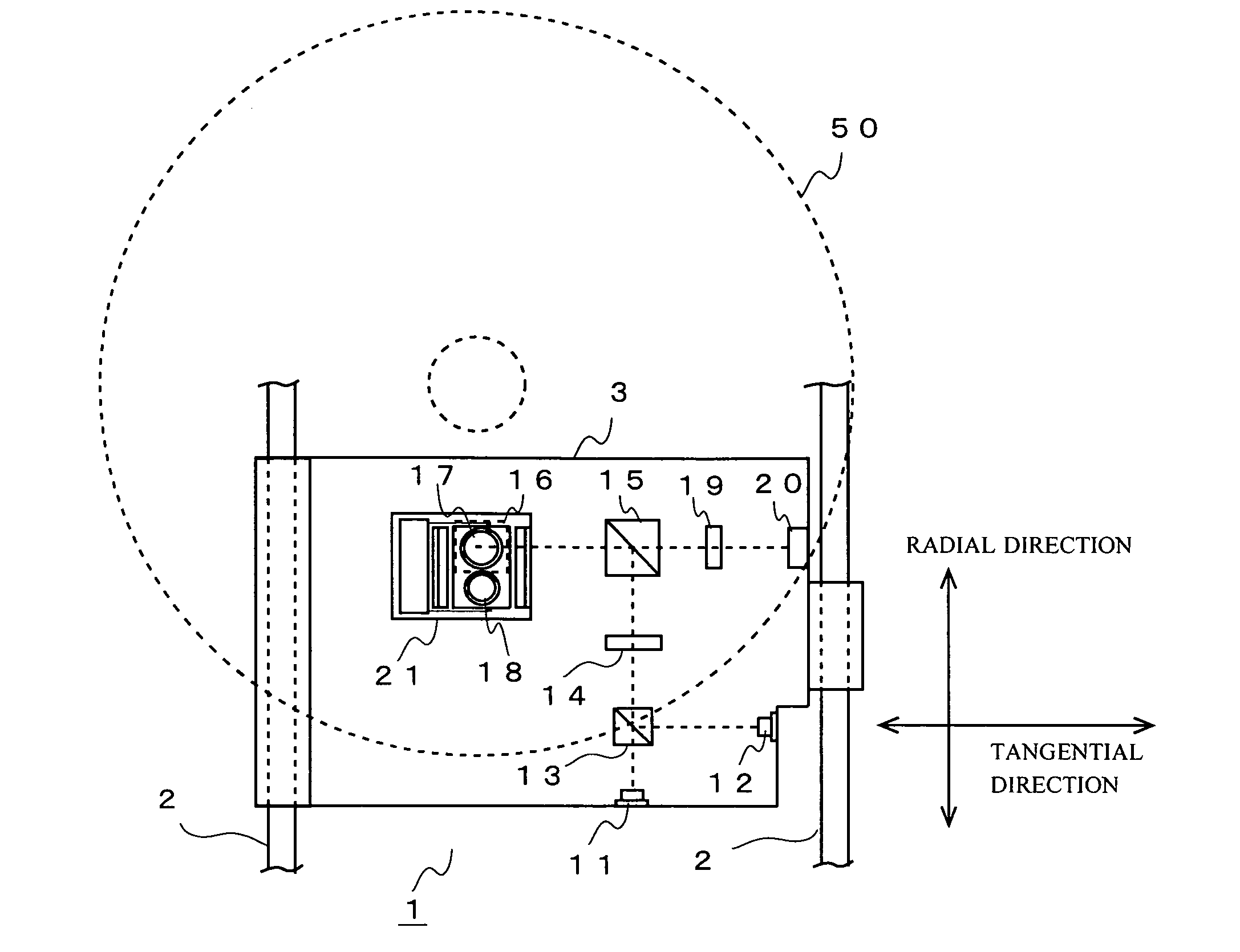
[0036]To begin with, the configuration of one embodiment of an optical pickup device 1 which has an objective lens actuator according to the present invention. FIG. 1 is a schematic plan view showing the configuration of the optical pickup device 1 of the embodiment. FIG. 1 shows those portions of the optical system of the optical pickup device 1 which are generally covered and not seen for easier explanation of the optical system.

[0037]The optical pickup device 1 of the embodiment is provided in such a way as to enable irradiation of a laser beam to three kinds (CD, DVD and BD) of optical discs (optical recording mediums) 50 to write and read information. The optical pickup device 1 is slidably supported on two guide rails 2 disposed in an optical disc unit having the optical pickup device 1...


PUM

PropertyMeasurementUnit
wavelengthaaaaaaaaaa

Abstract

An objective lens actuator includes a plurality of objective lenses, a first lens holder on which the plurality of objective lenses are mounted, and a drive mechanism that drives the first lens holder. At least one of the plurality of objective lenses is mounted on the first lens holder while being held by the second lens holder. Formed on the second lens holder are a slide part which slides the second lens holder with respect to the first lens holder at a time of assembly, and a projection arranged outward of the slide part and protruding toward the first lens holder with the second lens holder being mounted on the first lens holder. The lens holder has a groove formed therein where the projection is securely adhered.

Description

[0001]This application is based on Japanese Patent Application No. 2007-10983, filed on Jan. 22, 2007, and the contents of which are hereby incorporated by reference.BACKGROUND OF THE INVENTION[0002]1. Field of the Invention[0003]The present invention relates to an objective lens actuator to be equipped in an optical pickup device which irradiates a light beam to an optical recording medium to enable recording and reading information, and, more particularly, to the configuration of an objective lens actuator having a plurality of objective lenses. The present invention also relates an optical pickup device having such an objective lens actuator.[0004]2. Description of the Related Art[0005]Optical recording mediums, such as a compact disc (hereinafter called “CD”) and digital versatile disc (hereinafter called “DVD”), are popular. Further, studies have recently been made on enhancement of the density of optical recording mediums to increase the amount of information thereof, thereby ...

Claims


Application Information

Patent Timeline
Patent Type & Authority Applications(United States)
IPC IPC(8): G11B7/135
CPCG11B7/082G11B2007/0006G11B7/22G11B7/1374
Inventor HAYASHI, SOTAROHOSODA, RYOZO
Owner FUNAI ELECTRIC CO LTD
Why Eureka
Try Eureka