Coma aberration compensating device, coma aberration compensating method, and optical disc

a compensating device and aberration technology, applied in the field of optical discs, can solve the problems of reducing the reliability of recording or reproduction, reducing and unable to obtain sufficient system margin, so as to simplify the optimization of a coma aberration compensating unit and reduce the time required to perform adjustment. , the effect of reducing the siz

Inactive Publication Date: 2011-06-23
PIONEER CORP
View PDF2 Cites 1 Cited by
  • Summary
  • Abstract
  • Description
  • Claims
  • Application Information

AI Technical Summary

Benefits of technology

[0026]Therefore, the present invention has been made in view of the above problems, and it is an object of the present invention to provide a coma aberration compensating device with reduced size and a coma aberration compensating-method, wherein pickup-coma aberration is previously compensated for to reduce a load in a recording and reproducing device for the multi-layer optical disc.
[0027]It is another object of the present invention to provide a coma aberration compensating device with reduced size and a coma aberration compensating-method, wherein pickup-coma aberration is previously compensated for to simplify optimization of a coma aberration compensating unit and to significantly reduce the time required to perform adjustment when the user has loaded an optical disc.
[0039]In this coma aberration compensating-method, initially, the first coma aberration compensating unit is optimized such that remaining coma aberration is reduced with a light beam being focused on the optical disc surface, thereby compensating coma aberration (including no transmitted-layer-coma aberration) that is present only in the pickup optical system. Thereafter, the light beam is focused on a specific recording layer (preferably, the deepest layer) different from the optical disc surface and the second coma aberration compensating unit is then optimized such that remaining coma aberration is reduced with the light beam being focused on the specific recording layer, thereby compensating transmitted-layer-coma aberration. Accordingly, it is possible to quickly reduce total coma aberration of all recording layers.

Problems solved by technology

In the recording technology of the multi-layer optical disc, there is a problem of aberration, especially coma aberration, caused by the inclination of the optical axis of the light beam with respect to the normal line to the recording layers, which is referred to as a “tilt”.
To compensate the coma aberration is very important in the next generation multi-layer optical disc, because the coma aberration blurs the focal spot, reducing the recording or reproduction reliability.
Since it has been empirically shown that a sufficient system margin cannot be obtained unless the total coma aberration after adjustment is suppressed below about 15 mλ, reliable recording or reproduction is not performed on a recording layer with a depth of T≦50 μm or T≧150 μm.
Therefore, when the difference of transmitted layer's thicknesses between the rearmost and frontmost layers is greater than a right-side term of this equation, reliable recording or reproduction cannot be performed on all recording layers using the conventional coma aberration adjustment method.
However, practically, the total coma aberration including both the pickup-coma aberration and the transmitted-layer-coma aberration is compensated by changing the angle of the objective lens or the drive voltage of a liquid crystal panel for compensating coma aberrations since actual pickups inevitably have a pickup-coma aberration due to manufacturing errors of the optical system.

Method used


Image

  • Coma aberration compensating device, coma aberration compensating method, and optical disc
  • Coma aberration compensating device, coma aberration compensating method, and optical disc
  • Coma aberration compensating device, coma aberration compensating method, and optical disc

Examples


embodiment 1

[0134]The following is a description of a compensation process of coma aberration that is performed before recording or reproducing is performed on the optical disc 7 shown in FIG. 5 in a recording and reproducing device including the coma aberration compensating device shown in FIG. 13. Specifically, the compensation process of coma aberration is a procedure in which both the first coma aberration compensating step and the second coma aberration compensating step are performed until recording or reproducing is initiated when the user has loaded a disc into a recording and reproducing device in which a three-axes actuator serves as both a first radial coma aberration compensating device and a second radial coma aberration compensating device.

[0135]The compensation process of coma aberration shown in the flow chart of FIG. 20 is performed in the following manner.

[0136]First, the first coma aberration compensating step is performed. Specifically, when an optical disc 7 is inserted int...

embodiment 2

[0149]In Embodiment 2, compensation of coma aberration is performed in advance at the stage of assembling a recording and reproducing device at a factory. Here, the coma aberration compensating device shown in FIG. 13 is used to perform compensation of coma aberration.

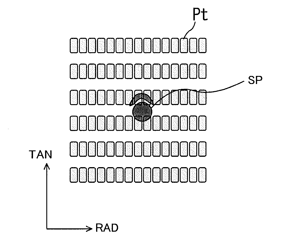
[0150]Specifically, a procedure shown in a flow chart of FIG. 23 is performed in the following manner. As described above, when the recording and reproducing device is assembled at the factory, it is possible to directly observe the spot shape at the first coma aberration compensating step and therefore it is possible to use a multi-layer disc without including any periodic pattern for compensation of the pickup-coma aberration formed on the surface of the optical disc, unlike the optical disc 7 of FIG. 5.

[0151]First, at the first coma aberration compensating step, a light beam is focused on the surface of a reference optical disc (step S1) and, with the beam being focused on the surface, a drive voltage of the TAN com...

embodiment 3

[0157]In a procedure according to Embodiment 3, a coma aberration compensating-method is performed at the factory using the coma aberration compensating device shown in FIG. 15. In this embodiment, liquid crystal panels for compensating the coma aberration in two directions (tangential and radial directions) are used as the first coma aberration compensating unit.

[0158]Specifically, a procedure shown in a flow chart of FIG. 22 is performed in the following manner.

[0159]First, at the first coma aberration compensating step, a light beam is focused on the surface of a reference optical disc (step S1) and, with the beam being focused on the surface, drive voltages of the compensation of coma aberration liquid crystal panels in two directions are optimized (steps S2 and S3). For example, the drive voltage of each liquid crystal panel can be optimized by adjusting the drive voltage while directly observing the shape of the beam spot over the reference optical disc, similar to Embodiment ...


PUM

PropertyMeasurementUnit
thicknessaaaaaaaaaa
depthaaaaaaaaaa
thicknessesaaaaaaaaaa

Abstract

A method for compensating the coma aberration in a pickup of a recording and reproducing device that records or reproduces data on or from an optical disc using the pickup is provided. The method includes a first coma aberration compensating step to compensate coma aberration in a body of an optical system including an objective lens for emitting a light beam to an optical disc including a plurality of recording layers and a second coma aberration compensating step to compensate coma aberration caused by relative inclination of the optical system with respect to the optical disc.

Description

TECHNICAL FIELD[0001]The present invention relates to an optical disc including a plurality of recording layers stacked in turn, on or from each of which information is capable of be recorded or reproduced by using an irradiation of a light beam, and more particularly to a coma aberration compensating device for compensating coma aberration in a recording and reproducing device for such a optical disc and a method therefor.BACKGROUND ART[0002]In recent years, an optical disc has been widely used as a recording medium on or from which data such as video data, audio data, or computer data is recorded or reproduced. For example, in Digital Versatile Disc (DVD) or Blu-ray disc (registered trademark) standards, a two layer disc having two recoding layers at one side thereof, from which reading is possible, has been practically used as a read-only or recordable disc.[0003]Data recorded on both a shallow recording layer and a deep recording layer of the two layer disc can be read from one ...

Claims


Application Information

Patent Timeline
Patent Type & Authority Applications(United States)
IPC IPC(8): G11B7/135G11B7/24G11B7/24038
CPCG11B7/0956G11B2007/0013G11B7/24038G11B7/13927
Inventor YANAGISAWA, TAKUMA
Owner PIONEER CORP
Why Eureka
Try Eureka