
Projection lens optical system

An optical system and projection lens technology, applied in the field of projection lens optical system, can solve the problems of high abrasive cost of aspherical lenses, affecting image quality, poor temperature stability, etc., and achieve excellent optical characteristics, improve imaging quality, and good consistency. Effect

Pending Publication Date: 2020-08-18
HUNAN CHIOPT OPTICAL TECH
View PDF0 Cites 1 Cited by
  • Summary
  • Abstract
  • Description
  • Claims
  • Application Information

AI Technical Summary

Problems solved by technology

The production of aspherical lenses requires high abrasive costs, which will inevitably lead to an increase in cost. Moreover, if it is a plastic aspheric surface, the temperature stability is too poor, and the image quality will be affected by the increase in temperature.

Method used

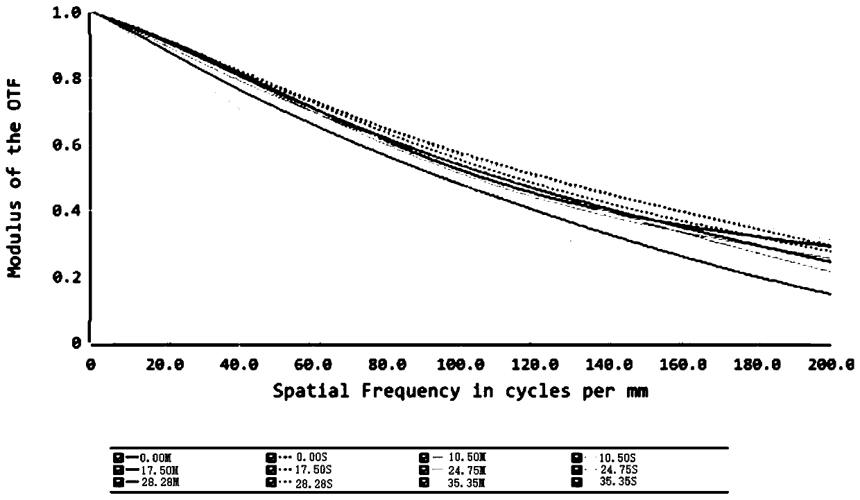
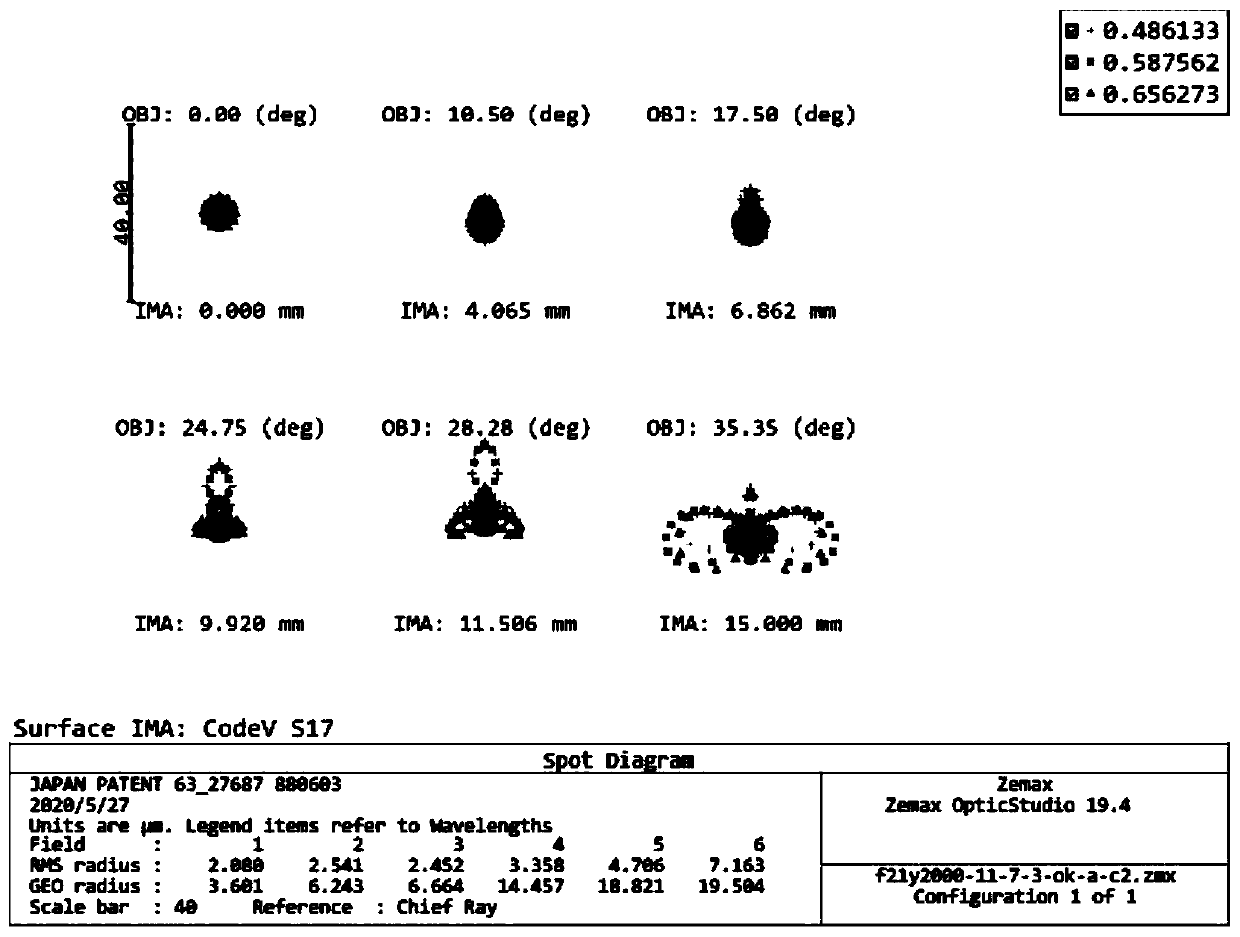

Image

  • Projection lens optical system
  • Projection lens optical system
  • Projection lens optical system

Examples


Embodiment

[0069] A projection lens optical system with a field angle of 70° belongs to a standard wide-angle lens. Through reasonable optical power distribution and material matching, various aberrations are compensated and corrected each other, so that when TV distortion is less than 2%, it still has high resolution and relative illuminance, thereby improving the quality of perception. The specific solutions are as follows:

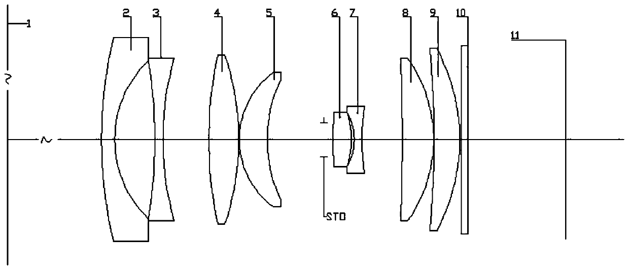
[0070] like figure 1 As shown, the optical system of the projection lens includes: wall 1, first lens 2, second lens 3, third lens 4, fifth lens 6, sixth lens 1, first lens 2, second lens 3, third lens 4, fifth lens 6, sixth The lens 7 , the seventh lens 8 , the eighth lens 9 , the protection panel 10 and the imaging target surface 11 . Preferably, the protective panel 10 is a protective lens made of glass with a thickness of 1 mm; the imaging target surface 11 is a slide; a diaphragm STO is provided between the fourth lens 5 and the fifth lens 6 .

[0071] For ...


PUM


Abstract

The invention provides a projection lens optical system. The optical system comprises a first lens, a second lens, a third lens, a fourth lens, a diaphragm, a fifth lens, a sixth lens, a seventh lens,an eighth lens and an imaging target surface which are sequentially arranged from an object side to an image side and share the same optical axis. According to the invention, a plurality of lenses are combined, and the design of focal power and shape structures of the first lens to the eighth lens and the position design of each lens are combined, so that the projection lens optical system is ina phi 30 large target surface range, on-axis and off-axis aberrations are fully corrected, the imaging quality is not obviously changed along with the view field, the consistency is good, and the optical characteristics are excellent.

Description

technical field [0001] The invention relates to the technical field of optical lenses, in particular to a projection lens optical system. Background technique [0002] A bright starry sky is the dream of most astronomy enthusiasts. In order to achieve a good look and feel, a projector can be used to project the starry sky onto the ceiling or wall, which requires the projector to have a long projection distance, a large projection area and a high relative illumination. However, in order to achieve the effect of large target surface, low distortion and high relative illumination, most projection instruments often use aspherical lenses. The production of aspherical lenses requires high cost of grinding tools, which will inevitably lead to an increase in cost. Moreover, if it is a plastic aspherical lens, the temperature stability is too poor, and the image quality will be affected due to the increase in temperature. [0003] To sum up, it is of great significance to design a p...

Claims


Application Information

Patent Timeline
Patent Type & Authority Applications(China)
IPC IPC(8): G02B13/00G02B1/00G03B21/14
CPCG02B13/005G02B1/00G03B21/14
Inventor 时爽罗吉祥宗刚群韦义壮
Owner HUNAN CHIOPT OPTICAL TECH
Learn More