Light emitting device, optical pickup apparatus and method for manufacturing the same

a technology of optical pickup and light emitting device, which is applied in the direction of semiconductor lasers, instruments, record information storage, etc., can solve the problems of difficulty in properly controlling, and deterioration of skew characteristics, so as to minimize the amount of coma aberration, optimize skew characteristics, and improve image height characteristics

Inactive Publication Date: 2012-11-01
SANYO ELECTRIC CO LTD +1
View PDF3 Cites 1 Cited by
  • Summary
  • Abstract
  • Description
  • Claims
  • Application Information

AI Technical Summary

Benefits of technology

[0015]According to the present invention, in the light emitting device emitting the first laser beam, the second laser beam having a wavelength longer than that of the first laser beam and the third laser beam having a wavelength longer than those of the first and second laser beams, the third light emitting source emitting the third laser beam compatible with a disk having the worst image height characteristics is disposed on the optical axis of the objective lens. This minimizes the amount of coma aberration generated in the third laser beam poor in image height characteristics, thereby optimizing the skew characteristics in the whole light emitting device even if a certain amount of coma aberration is generated in the other two laser beams.
[0016]Moreover, according to the present invention, the first light emitting source emitting the first laser beam is disposed to one side of the third light emitting source, and the second light emitting source emitting the second laser beam is disposed to the other side of the third light emitting source. In this way, in the case of a three-wavelength compatible objective lens having a characteristic that a phase direction of the coma aberration generated in the second laser beam is opposite to that of the coma aberration generated in the third laser beam, a phase direction of the coma aberration generated when the first laser beam passes through the objective lens coincides with the phase propagation direction of the coma aberration in the second laser beam. Accordingly, a relative inclination between the objective lens and the incident laser beam is adjusted so as to minimize the coma aberration in one of the first and second laser beams, thereby enabling correction to reduce the coma aberration in both of the laser beams.

Problems solved by technology

Such poor image height characteristics of the laser beam for CD make it difficult to properly control the coma aberration in reading or writing on a CD by use of the laser beam focused by the objective lens, and thereby poses a problem of deterioration in skew characteristics.
Therefore, adjustment made to minimize the coma aberration in the laser beam for CD or the laser beam for BD increases the coma aberration in the laser beam for DVD, and thus causes a problem of deterioration in skew characteristics.

Method used


Image

  • Light emitting device, optical pickup apparatus and method for manufacturing the same
  • Light emitting device, optical pickup apparatus and method for manufacturing the same
  • Light emitting device, optical pickup apparatus and method for manufacturing the same

Examples


first embodiment

Light Emitting Device

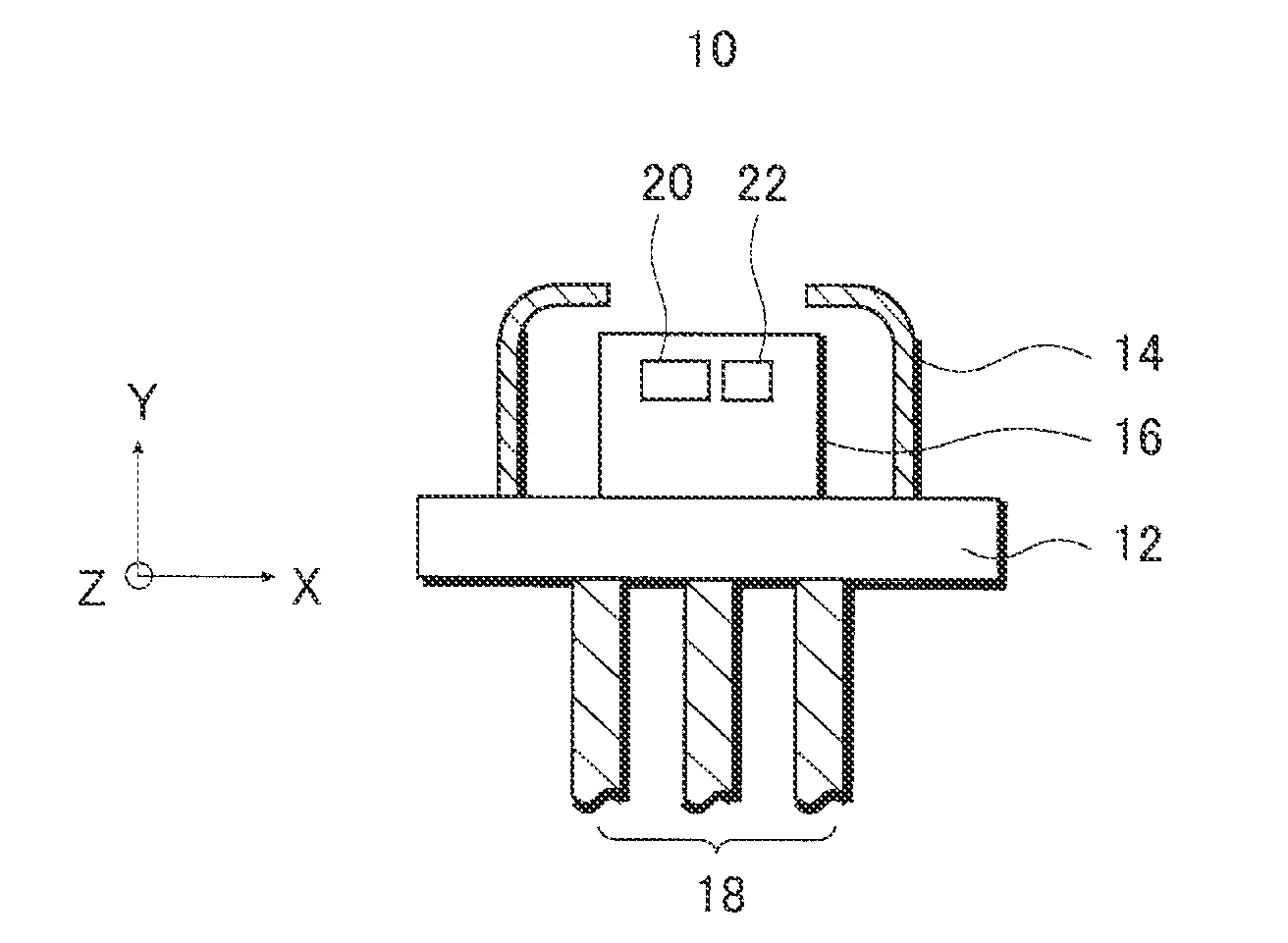
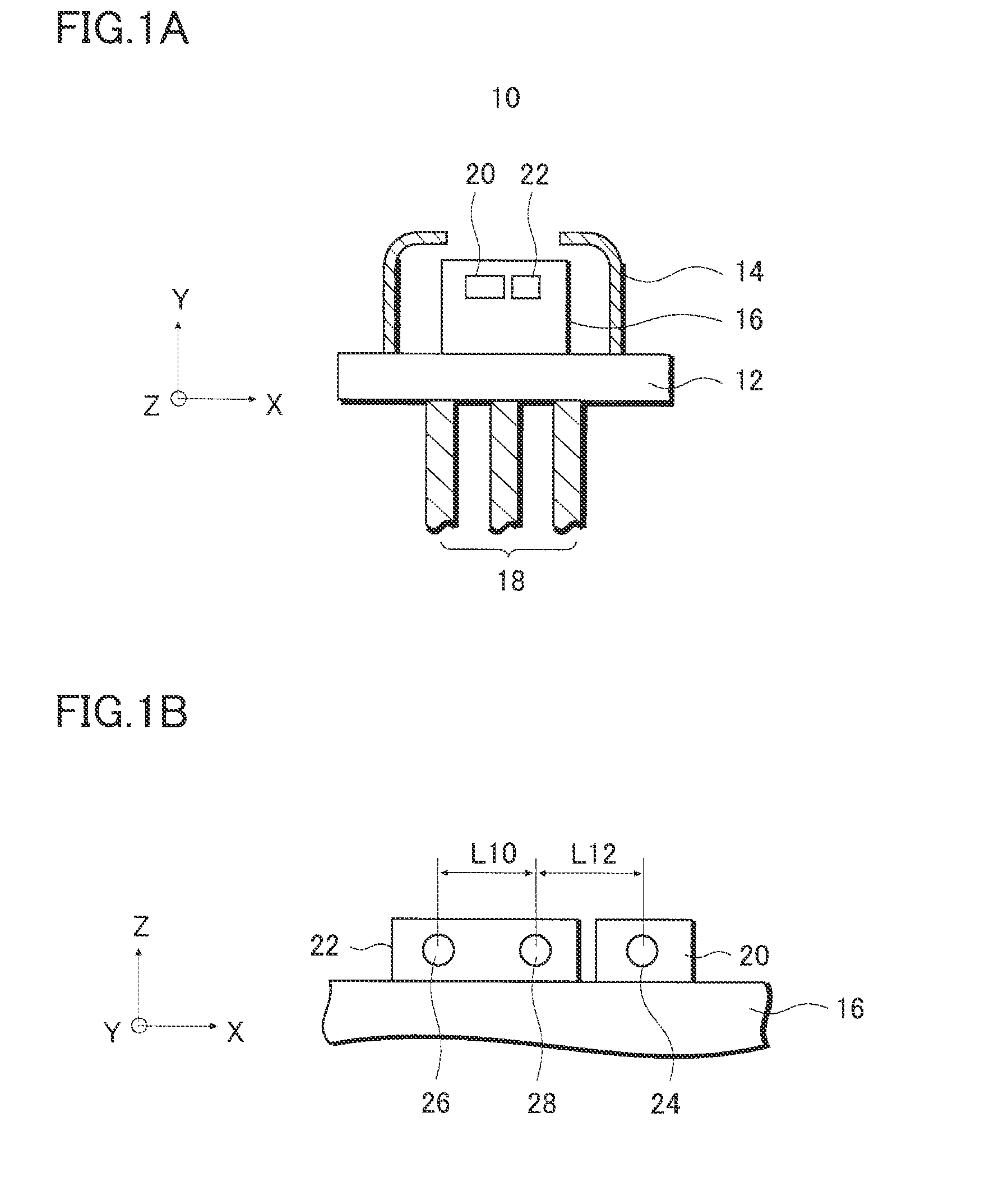
[0026]With reference to FIGS. 1A and 1B, a configuration of a light emitting device 10 of this embodiment will be described. FIG. 1A is a cross-sectional view of the light emitting device 10 seen from the side, and FIG. 1B is a view of a portion in which light emitting chips are mounted, as seen from above the page.

[0027]Here, in this embodiment, description is given using X, Y and Z axes orthogonal to each other. The Y axis is an axis parallel to a travelling direction of a laser beam emitted from the light emitting device 10. The X axis is an axis parallel to a direction in which a first light emitting chip 20 and a second light emitting chip 22 are aligned. The Z axis is an axis in a direction vertically penetrating the page. Also, multiple light emitting points provided on both the light emitting chips are arranged on the Z-X plane.

[0028]With reference to FIG. 1A, the light emitting device 10 is a CAN type package, mainly including: an approximately disk-sha...

second embodiment

Optical Pickup Apparatus

[0055]In this embodiment, with reference to FIG. 4, description is given of a structure of an optical pickup apparatus 30 including the light emitting device 10 described in the first embodiment.

[0056]The optical pickup apparatus 30 is, in general, an apparatus for applying a laser beam to a rotating disk 48 (optical recording medium) and detecting the laser beam reflected by the disk 48, and is used as mounted on an information recorder / reproducer such as a disk reproducer.

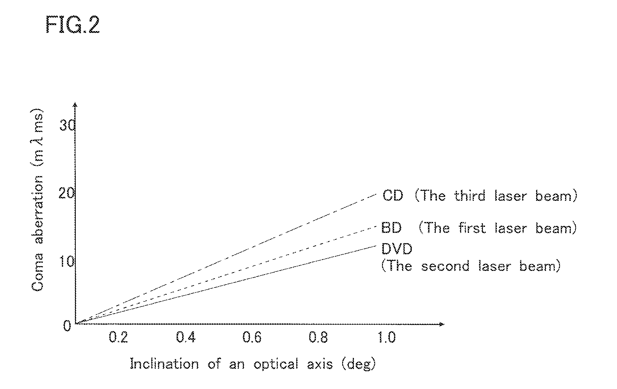
[0057]The optical pickup apparatus 30 mainly includes: a light emitting device 10 configured to emit three kinds of laser beams having different wavelengths; a first PDIC 42 configured to detect a laser beam of the BD standard; a second PDIC 44 configured to detect laser beams of the CD standard and the DVD standard; and various optical elements disposed on optical paths thereamong. The respective optical elements shown in FIG. 4 are included in a housing formed by injection molding magnes...

third embodiment

Method for Manufacturing Optical Pickup Apparatus

[0087]With reference to FIGS. 5 to 8, description is given of a method for manufacturing the optical pickup apparatus having the configuration described in the second embodiment.

[0088]With reference to FIG. 5, the method for manufacturing the optical pickup apparatus according to this embodiment mainly includes: a first step S11 of positioning a light emitting unit; a second step S12 of positioning a second light receiving region (DVD light receiving region) included in the second PDIC 44; a third step S13 of positioning a third light receiving region (CD light receiving region) included in the second PDIC 44; and a fourth step S14 of positioning a first light receiving region (BD light receiving region) included in the first PDIC 42.

[0089]Here, the first PDIC 42 described above is for detecting the first laser beam for BD, and the second PDIC 44 is for detecting the second laser beam for DVD and the third laser beam for CD.

[0090]Alth...


PUM

PropertyMeasurementUnit
blue-violet wavelength rangeaaaaaaaaaa
red wavelength rangeaaaaaaaaaa
infrared wavelength rangeaaaaaaaaaa

Abstract

In the present invention, to improve CD read / write characteristics having poor image height characteristics, a third light emitting source emitting a third laser beam for CD is disposed on an optical axis of an objective lens. Thereby, the third laser beam emitted from the third light emitting source travels along the optical axis of the objective lens, thus generating no coma aberration in the third laser beam. Furthermore, in the present invention, a second light emitting source emitting a second laser beam for DVD and a first light emitting source emitting a first laser beam for BD are disposed across the third light emitting source. Thereby the phase propagation directions of coma aberrations in the first and second laser beams coincide with each other. Adjustment of the coma aberration in one of the laser beams enables the coma aberration in the other laser beam to be adjusted.

Description

REFERENCE TO RELATED APPLICATIONS[0001]This application is a divisional of U.S. patent application Ser. No. 12 / 986,595, filed Jan. 7, 2011, which claims priority from Japanese Application No. 2010-002702, filed Jan. 8, 2010, the entire contents of which are incorporated herein by reference.BACKGROUND OF THE INVENTION[0002]1. Field of the Invention[0003]The present invention relates to a light emitting device irradiating multiple optical recording media with laser beams. The present invention also relates to an optical pickup apparatus including such a light emitting device, and a method for manufacturing the same.[0004]2. Description of the Related Art[0005]For optical pickup apparatuses compatible with multiple standards of optical recording media, various measures have been made for reduction in size and weight, and other purposes. For example, one of the measures is to employ an objective lens compatible with lasers of many wavelengths. Some of optical pickup apparatuses of this ...

Claims


Application Information

Patent Timeline
Patent Type & Authority Applications(United States)
IPC IPC(8): G11B7/1275
CPCG11B7/1275G11B7/131H01S5/4087H01S5/005H01S5/02212G11B7/22
Inventor KAWASAKI, RYOICHIHOTTA, TOHRU
Owner SANYO ELECTRIC CO LTD
Why Eureka
Try Eureka