Two-Stage Two-Speed Front Differential

Active Publication Date: 2008-09-18
GKN DRIVELINE NORTH AMERICA
View PDF70 Cites 19 Cited by
  • Summary
  • Abstract
  • Description
  • Claims
  • Application Information

AI Technical Summary

Benefits of technology

[0007]The present invention is advantageous in that two-stage aspect of the design permits design flexibility in ter

Problems solved by technology

In vehicles where it is desirable to provide a very low range (creep) drive mode, however, the veh

Method used


Image

  • Two-Stage Two-Speed Front Differential
  • Two-Stage Two-Speed Front Differential
  • Two-Stage Two-Speed Front Differential

Examples


Embodiment Construction

[0020]In the following description, various operating parameters and components are described for one constructed embodiment. These specific parameters and components are included as examples and are not meant to be limiting.

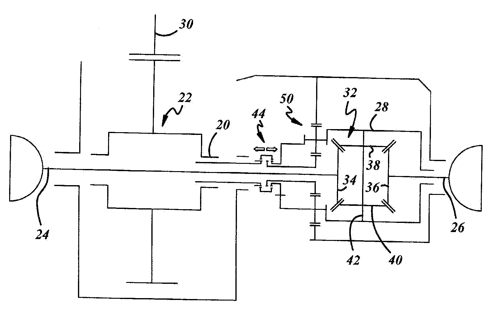
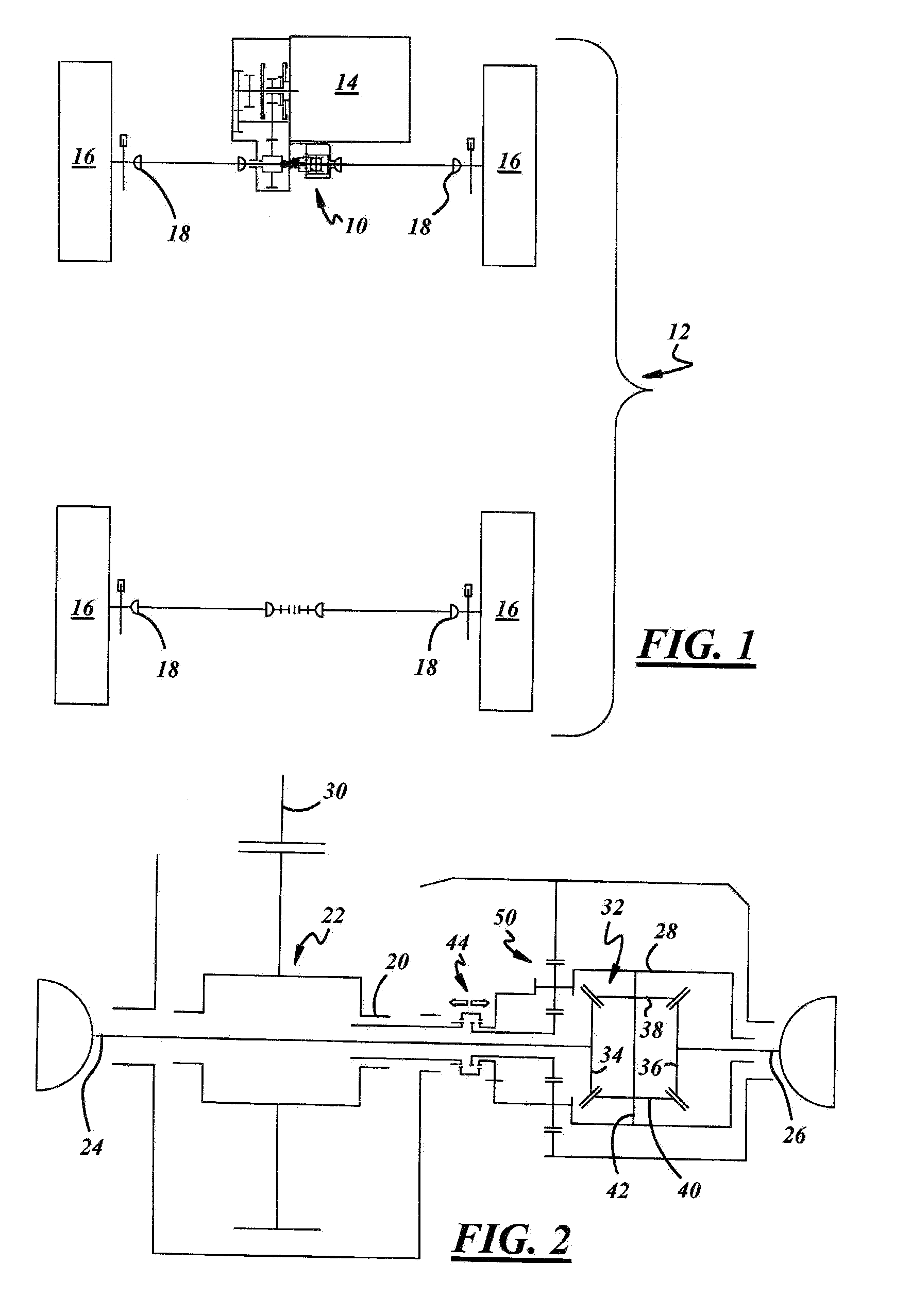
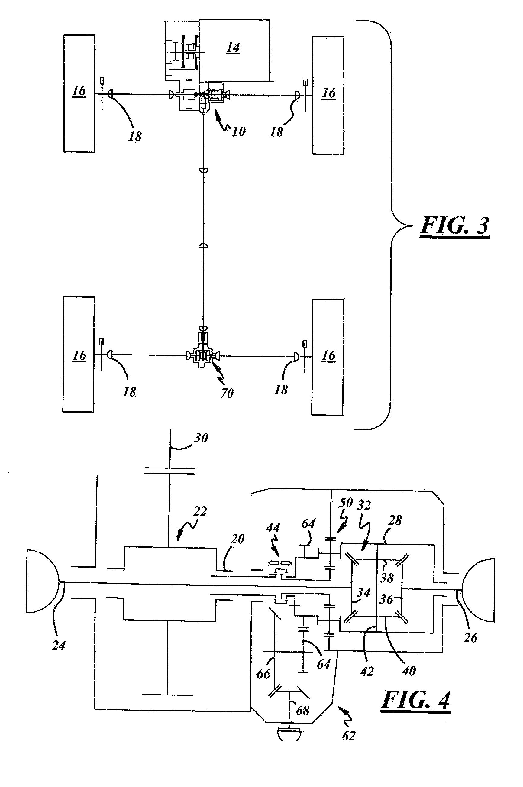
[0021]Referring now to FIGS. 1 and 2 which are schematics of a variable speed differential assembly 10 in accordance with the present invention. The vehicle 12, represented schematically, is illustrated as a front wheel drive vehicle with transverse engine 14 mounting. The vehicle 12 includes a plurality of wheels 16 and joints 18 as customary but is not intended to be limiting. Similarly, the engine 14 supplies torque to an input shaft 20 via a spool 22 or similar device. A first side shaft 24 and a second side shaft 26 meet in an offset differential case 28. The differential case 28 is offset and is not directly in line with the transverse final drive 30. Within the differential case 28 is contained a differential mechanism 32 engaging the side shafts 24,26. I...


PUM


Abstract

A variable speed front differential assembly for a vehicle is provided including a first side shaft, a second side shaft, and an input shaft. An offset differential case houses a differential mechanism engaging the first side shaft and the second side shaft. A speed selection assembly is movable from a first speed position to a second speed position. A speed reduction assembly is mounted adjacent the offset differential case. The speed selection assembly directly engages the offset differential case housing when in the first speed position such that a 1:1 drive ratio is achieved. The speed selection assembly engages the offset differential case through the speed reduction assembly when in the second speed position such that an increased drive ratio is achieved.

Description

TECHNICAL FIELD[0001]The present invention relates to a front differential for an all-wheel drive vehicle. In particular, the invention concerns a two-stage two-speed front differential.BACKGROUND OF THE INVENTION[0002]Motor vehicles driven by a plurality of axles can be divided into those with a hang-on four-wheel drive wherein a primary axle is driven permanently and a secondary axle is connected if required; and those with a permanent four wheel drive wherein both axles are driven permanently. The design of the driveline is largely influenced by the arrangement of the engine in the motor vehicle, i.e. whether it is arranged in the front or at the rear and whether it is positioned in the longitudinal or transverse direction. At the same time, stringent packaging requirements exist regarding size, weight, and assembly costs of such systems.[0003]In a typical front-wheel-drive based all-wheel-drive hang on layout, the engine is transversely mounted, and the front differential is inc...

Claims


Application Information

Patent Timeline
IPC IPC(8): F16H48/06G06F17/00
CPCB60K17/346F16H48/08F16H3/54B60K17/3467
Inventor PEURA, BRENT MICHAEL
Owner GKN DRIVELINE NORTH AMERICA
Why Eureka
Try Eureka