Heating system

Inactive Publication Date: 2002-12-05
ROBERT BOSCH GMBH
View PDF0 Cites 12 Cited by
  • Summary
  • Abstract
  • Description
  • Claims
  • Application Information

AI Technical Summary

Problems solved by technology

In some operating states of an internal combustion engine, such as cold starting, short trips, or long downhill trips by motor vehicles, the heat input into the coolant from the engine itself is no longer sufficient, especially if the efficiency of the engine is very high, as in the case of direct gasoline injection, high pressure diesel injection with a common rail, or a highly charged engine with a turbocharger, since then only slight heat losses occur.
Accordingly, the engine and its catalytic converter do not reach their optimal temperatures within the brief available time, or do so only quite late, wh

Method used


Image

  • Heating system
  • Heating system

Examples


Example

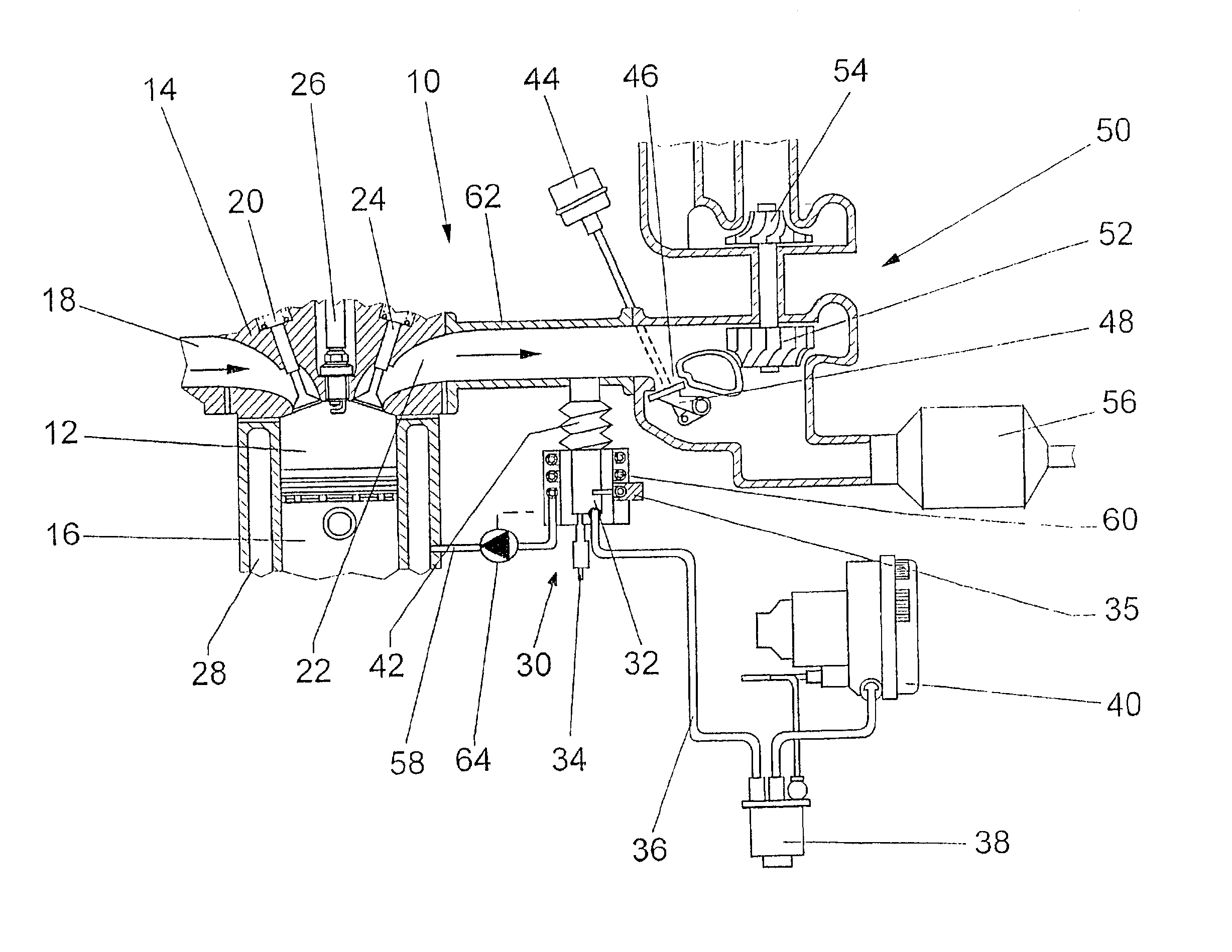
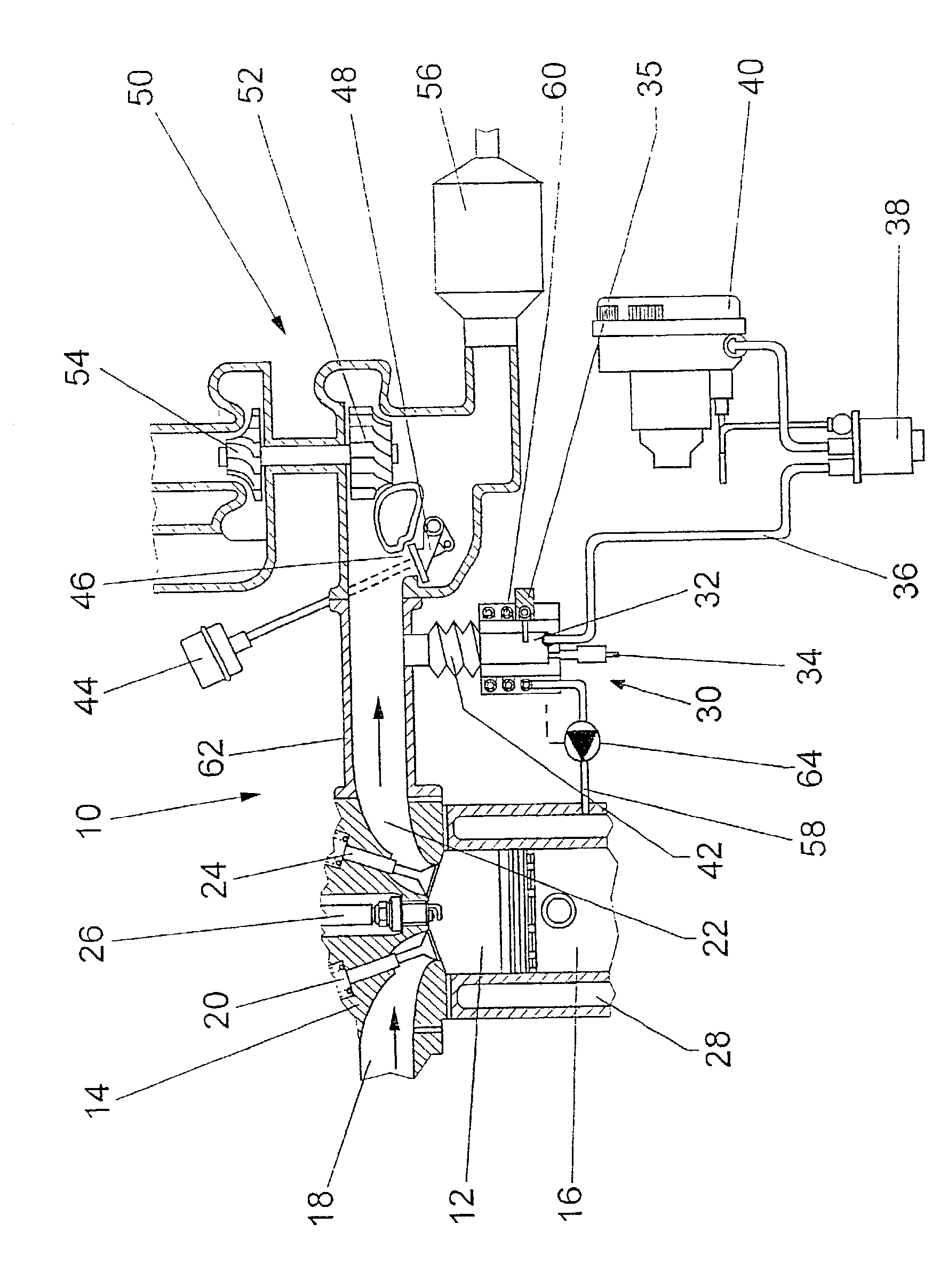
[0010] The internal combustion engine 10 has cylinders 12, which between pistons 16 and a cylinder head 14 form work chambers, to which air is delivered via inlet conduits 18. Via outlet conduits 22, the piston 16 expels the exhaust gas into an exhaust manifold 62. The inlet conduits 18 and the outlet conduits 22 are controlled by inlet valves 20 and outlet valves 24, respectively. An ignition aid 26, in the form of a spark plug in the case of the Otto process, initiates the combustion of the fuel-air mixture in the cylinder 12, while an ignition aid 26, in the form of a glow plug in the diesel process, serves to preheat the combustion air.

[0011] A combustion chamber 32 of a heater 30 is connected to the exhaust manifold 62 of the engine 10 via an exhaust line 42. The exhaust line 42 is expediently embodied as a metal bellows, so that it can compensate for different thermal expansions as a consequence of different temperatures between the combustion chamber 32 and the exhaust manifo...


PUM


Abstract

The invention is based on a heating system for a motor vehicle, which is driven by an internal combustion engine (10), in which a heater (30) includes a combustion chamber (32) with a fuel injection device (34) and an ignition device (35) and also includes an air blower (40), and is triggered as a function of operating parameters and/or ambient parameters of the motor vehicle and/or of the internal combustion engine (10) or by actuating signals. It is proposed that the combustion chamber (32) is connected to the exhaust system (62) of the internal combustion engine (10) in the region of an exhaust manifold (62) of the internal combustion engine (10), between outlet valves (24) and a exhaust gas catalytic converter (56), via an exhaust line (42).

Description

PRIOR ART[0001] The invention is based on a heating system as generically defined by the preamble to claim 1.[0002] In some operating states of an internal combustion engine, such as cold starting, short trips, or long downhill trips by motor vehicles, the heat input into the coolant from the engine itself is no longer sufficient, especially if the efficiency of the engine is very high, as in the case of direct gasoline injection, high pressure diesel injection with a common rail, or a highly charged engine with a turbocharger, since then only slight heat losses occur. Accordingly, the engine and its catalytic converter do not reach their optimal temperatures within the brief available time, or do so only quite late, which leads to increased fuel consumption and increased exhaust emissions.[0003] Since at low outdoor temperatures considerable amounts of heat are required to de-ice the vehicle windows or to heat the passenger compartment, both driving safety and comfort are restricte...

Claims


Application Information

Patent Timeline
IPC IPC(8): F01N13/08F01N3/20F01P5/12F01P7/14F02B37/12F02B37/18F02B37/20
CPCF01N3/2033F01N2240/02F01N2470/12F01P2005/125F01P2007/146F01P2060/18Y02T10/26F02B37/20F23N2033/06F23N2035/30F23N2041/14Y02T10/144F02B37/18F23N2233/06F23N2235/30F23N2241/14Y02T10/12Y02A50/20F01N3/38
Inventor BAEUERLE, MICHAELRIES-MULLER, KLAUS
Owner ROBERT BOSCH GMBH
Why Eureka
Try Eureka