Exhaust manifold for four-cylinder engine

a four-cylinder engine and exhaust manifold technology, applied in the field of four-cylinder engines, can solve the problems of output torque and output torque decline, and achieve the effects of reducing the cost of an exhaust gas system, reducing the temperature of an exhaust gas, and shortening the catalyst activation period

Inactive Publication Date: 2005-11-08
NISSAN MOTOR CO LTD
View PDF28 Cites 13 Cited by
  • Summary
  • Abstract
  • Description
  • Claims
  • Application Information

AI Technical Summary

Benefits of technology

[0003]In order to shorten a catalyst activation period after an engine is started and aiming at cost reduction of an exhaust gas system, a length of an exhaust manifold from an exhaust port outlet of a cylinder head to a manifold catalyst inlet or a gas contact length inside the exhaust manifold is reduced, thereby restraining a temperature decrease of an exhaust gas and improving temperature rise performance of a catalyst.
[0009]As a result, since a pressure in the vicinity of the exhaust valve during the exhaust stroke increases, scavenging of a combustion gas in the cylinder deteriorates and an engine torque at low and intermediate ranges is reduced.
[0011]However, a total length of the exhaust manifold becomes as long as an independent portion of the exhaust manifold branches, thereby decreasing an exhaust gas temperature at a manifold catalyst inlet and lengthening time for catalyst activation.
[0014]As a result, the total length of the exhaust manifold gets long, the exhaust temperature decreases at the manifold catalyst inlet, and the catalyst activation time is lengthened.
[0015]Moreover, the branch converging angle is large and a propagation path of the pressure wave of the exhaust gas easily goes around through the converging portion, thereby creating an engine torque reduction at low and intermediate speed ranges due to exhaust gas interference on its own cylinder.

Problems solved by technology

On the other hand, as a consequence of the above technology, an engine output torque decreases at a fully opened position of a throttle valve in low and intermediate speed ranges due to increase of exhaust gas interference caused by shortening an exhaust manifold branch or the output torque decreases in a high speed range due to increase of air flow resistance caused by narrowing the exhaust manifold and adding a manifold orifice.

Method used


Image

  • Exhaust manifold for four-cylinder engine
  • Exhaust manifold for four-cylinder engine
  • Exhaust manifold for four-cylinder engine

Examples


first embodiment

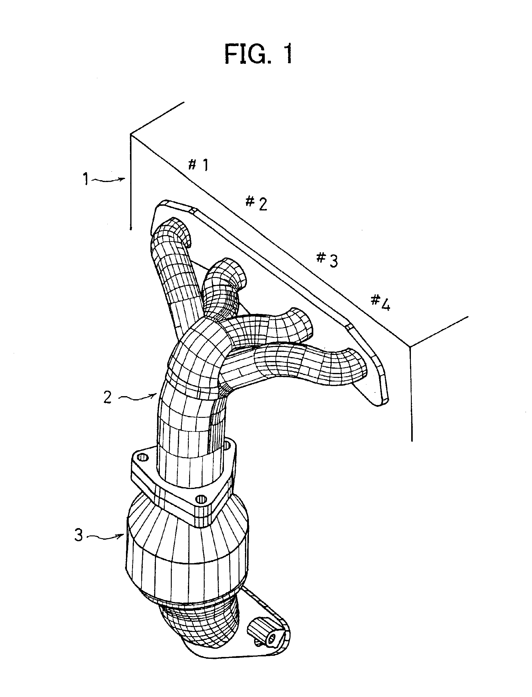
[0037]FIG. 1 is a schematic perspective view of an engine and an exhaust manifold of a first embodiment according to the invention.

[0038]An engine 1 is a four-cylinder engine where a firing (for example, spark or ignition) thereof is carried out in the order of cylinder #1, cylinder #3, cylinder #4, and cylinder #2. An exhaust manifold 2 is mounted to a cylinder head side and connected to an exhaust port outlet for each cylinder and a manifold catalyst 3 is mounted to an outlet of exhaust manifold 2.

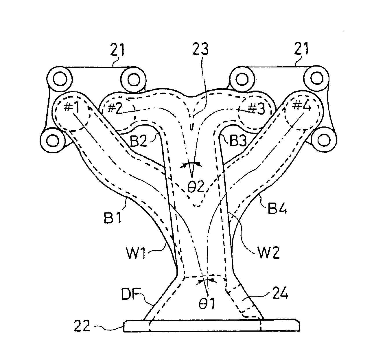
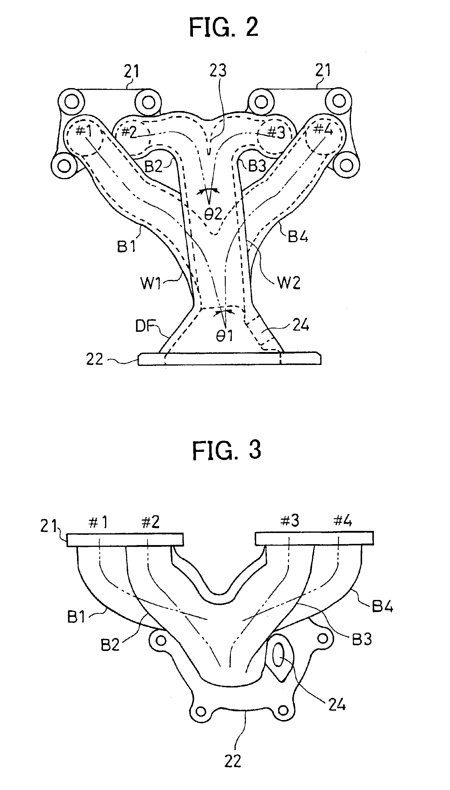
[0039]Exhaust manifold 2 will be explained in more detail with reference to FIG. 2-FIG. 5. FIG. 2 is an elevation view of exhaust manifold 2, FIG. 3 is a plan view thereof, FIG. 4 is a side view thereof, and FIG. 5 is a bottom view thereof.

[0040]Exhaust manifold 2 comprises branches B1-B4 connected respectively to the exhaust port outlet of each cylinder of engine 1 through a flange 21, a convergence branch W1 where branch B1 of cylinder #1 and branch B4 of cylinder #4 that are not fired...


PUM


Abstract

In an exhaust manifold of a four-cylinder engine four cylinders of which line up in order of cylinder #1, cylinder #2, cylinder #3 and cylinder #4, temperature rise performance of a manifold catalyst improves by shortening a total length of the exhaust manifold while preventing exhaust gas interference between the cylinders. Therefore, an exhaust manifold branch of cylinder #1 and an exhaust manifold branch of cylinder #4 in outward sides of the engine that are not fired in succession are made convergent with its convergence angle θ1 being equal to or below 20 degrees to form a first convergent exhaust manifold branch and an exhaust manifold branch of cylinder #2 and an exhaust manifold branch of cylinder #3 between the cylinder #1 and cylinder #4 that are not fired in succession are made convergent at a minimum distance having a laterally projected shape to form a second convergent exhaust manifold branch. The first and the second convergent exhaust manifold branches are thereafter convergent at a convergence angle θ3 from 0 degrees to 20 degrees.

Description

FIELD OF THE INVENTION[0001]The present invention relates to a four-cylinder engine, and in particular, to an exhaust manifold thereof.RELATED ART OF THE INVENTION[0002]In an earlier four-cylinder engine, an exhaust manifold branch of a cylinder is convergent with an exhaust manifold branch of a different cylinder that is not fired subsequent to ignition of the cylinder. That is, when an ignition is carried out in an order of cylinder #1-cylinder #3-cylinder #4-cylinder #2, an exhaust manifold branch of cylinder #1 converges into an exhaust manifold branch of cylinder #4 and an exhaust manifold branch of cylinder #2 converges into an exhaust manifold branch of cylinder #3 (Japanese Unexamined Utility Publication No. 1-66424, Japanese Unexamined Utility Publication No. 2-101017, Japanese Unexamined Utility Publication No. 2-103120 and Japanese Examined Utility Publication No. 2-24897).SUMMARY OF THE INVENTION[0003]In order to shorten a catalyst activation period after an engine is st...

Claims


Application Information

Patent Timeline
Patent Type & Authority Patents(United States)
IPC IPC(8): F01N7/10F01N7/00F02B27/00F01N3/28F01N7/08F02B27/04F01N13/10F01N13/08F01N13/18F02D13/02
CPCF01N3/28F01N13/08F01N13/10F02B27/04Y02T10/146Y02T10/12
Inventor ASHIDA, MASAAKINISHIZAWA, KIMIYOSHI
Owner NISSAN MOTOR CO LTD
Why Eureka
Try Eureka