Systems, methods and devices for performing gynecological procedures

a gynecological and system technology, applied in the field of systems, methods and devices for performing gynecological procedures, can solve the problems of difficult use of gynecologic products, limited use and functionality, and most often performed in hospitals for gynecologic treatment, and achieve the effect of preventing painful and potentially destructive dilation of the cervix

Active Publication Date: 2008-10-09
HOLOGIC INC
View PDF74 Cites 485 Cited by
  • Summary
  • Abstract
  • Description
  • Claims
  • Application Information

AI Technical Summary

Benefits of technology

[0007]According to a first aspect of the invention a hysteroscopic morcellator for performing a gynecologic procedure is disclosed. Hysteroscopic morcellator system (FIG. 1, 100) can include without limitation a slidably receivable visualization means preferably <1.5 mm (for example, a fiber optic scope); an independent aspiration and / or irrigation means; and a tissue removal means such that the combined outer diameters of the multiuse device or separate devices can be placed through body cavity or sheath that has an outer diameter (OD) preferably less than 9 mm, and preferably less than 8 mm, and preferably less than 7 mm, and preferably less than 6 mm, and preferably less than 5 mm, such as to prevent painful and potentially destructive dilation of the cervix is disclosed.
[0008]According to another aspect of the invention, the morcellator system can comprise two independent subassemblies such that they that operate together as a single tool that combines one or more functions of cervical distention, uterine distention, visualization, and therapy is disclosed. The first subassembly provides the power means for the morcellation means. The second subassembly contains the aspiration and irrigation ports and the moreellation means. The second subassembly contains all of the body fluid and tissue contacting elements and reduces the interface for the two subassemblies to a single rotating shaft. By separating these two elements, sterilization will only be required for the second subassembly allowing it to be manufactured as a single use disposable device. The power subassembly, which will be battery operated, can be cleaned and reused. The tool or tools combined OD is to be less than 9 mm but preferably less than 8 mm, and preferably less than 7 mm, and preferably less than 6 mm, and preferably less than 5 mm such as to prevent painful and potentially destructive dilation of the cervix. In a preferred embodiment, second subassembly includes a sterile bag which can surround power subassembly such as when second subassembly is attached to power subassembly. In another preferred embodiment, the second subassembly includes an elongate shaft with one or more lumens. These one or more lumens may include a mechanical key such as to orient one or more inserted devices, such as visualization means.
[0009]According to another aspect of the invention, the morcellator configuration for the aforementioned system is composed of two or more members with cutting edges and each of these members connected together on a shaft such that they that rotate together as a single tool but one that permits two or more cuts to be made with each rotation of the assembly. By creating multiple cutting elements the speed of the tissue resection will be improved reducing the procedure time. By reducing the procedure time, the risks for anesthesia, fluid intravasation, injury, perforation and distention will be reduced. The morcellator outer diameter is to be less than 7 mm but preferably less than 6 mm, and preferably less than 5 mm, and preferably less than 4 mm, and preferably less than 3 mm, and in some instances less than 2 mm in size, such as to prevent painful and potentially destructive dilation of the cervix.

Problems solved by technology

Currently available gynecologic products are difficult to use and often have limited use and functionality.
Treatment of gynecologic disorders and ailments is most often performed in a hospital and bears a large cost due to the setting and the support personnel required.
Treatment options and modalities are also limited, such that the patient may not be offered the best option for her particular condition.

Method used


Image

  • Systems, methods and devices for performing gynecological procedures
  • Systems, methods and devices for performing gynecological procedures
  • Systems, methods and devices for performing gynecological procedures

Examples


Embodiment Construction

[0060]To facilitate an understanding of the invention, a number of terms are defined immediately herebelow.

DEFINITIONS

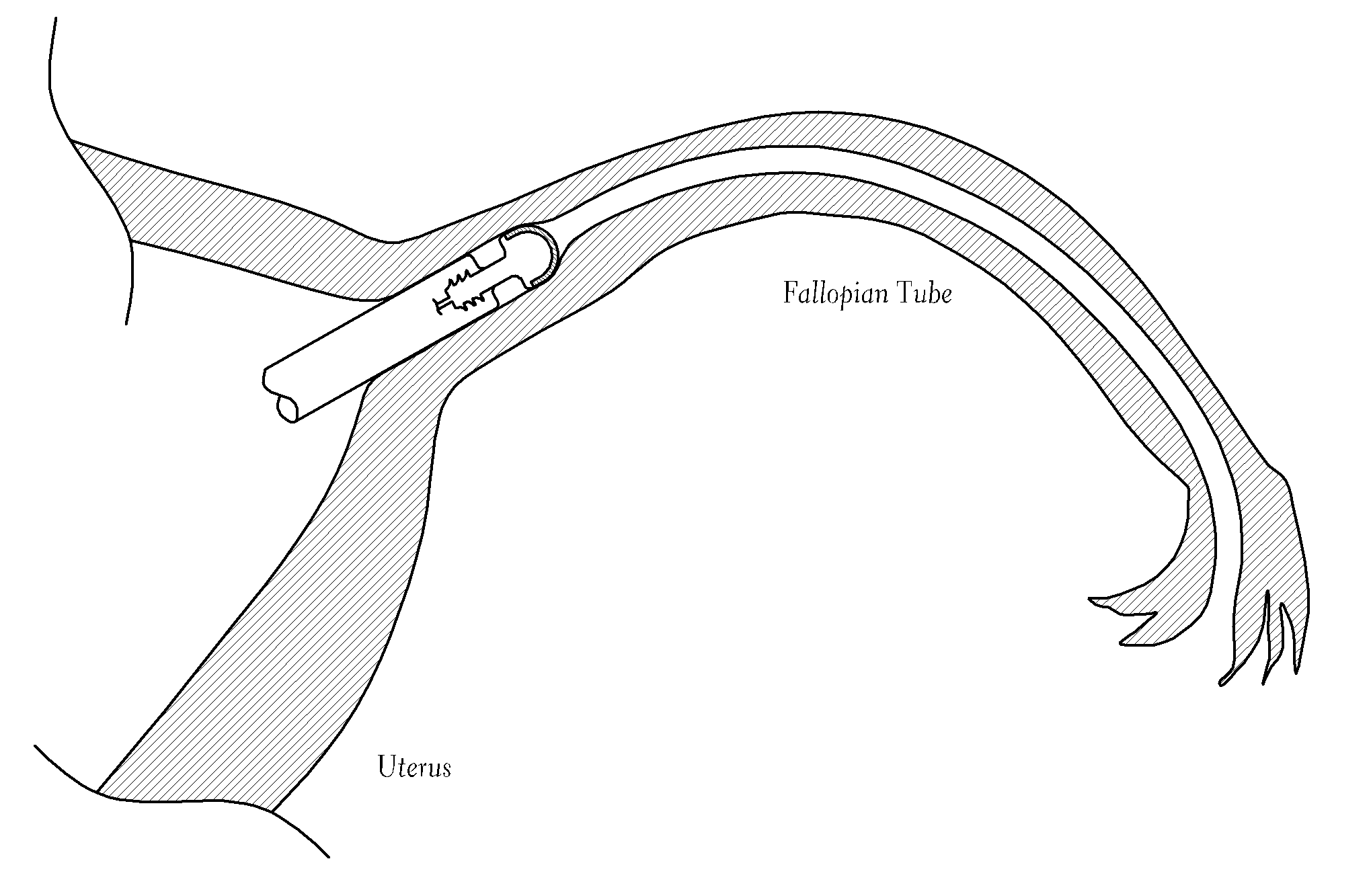
[0061]As used herein, the term “trans-vaginal-wall” refers to devices or procedures which enter the vaginal opening, travel down the vaginal canal, and exit through the vaginal wall proximal to the cervix.

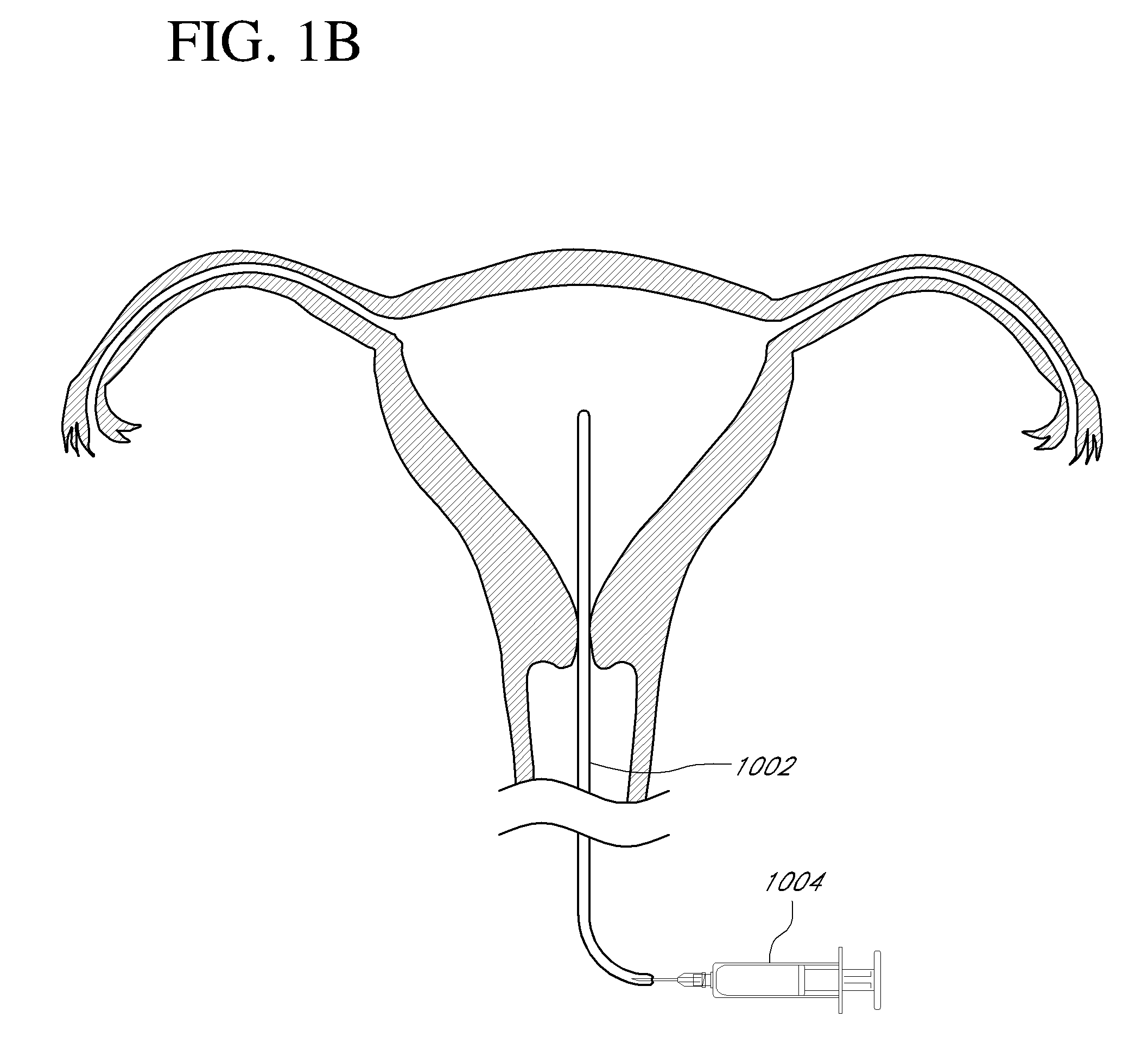
[0062]As used herein, the term “trans-cervical” refers to devices or procedures which enter the vaginal opening, travel down the vaginal canal, pass through the cervical canal and enter the uterus.

[0063]As used herein, the term “trans-uteral” refers to devices or procedures which pass through the wall of the uterus.

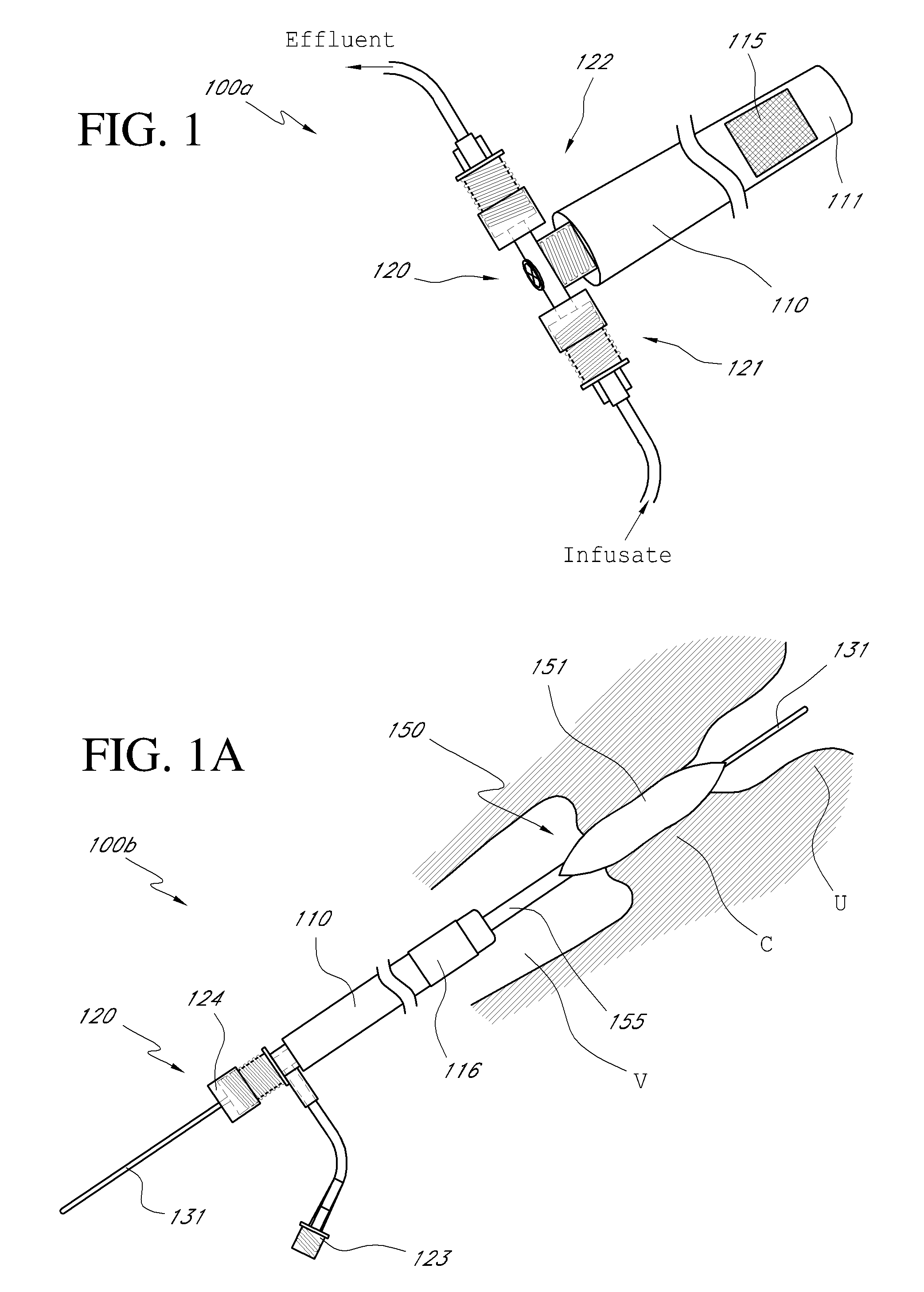
[0064]As used herein, the term “drug” refers to all drugs and other agents that may be included in the systems, methods apparatus and devices of the present invention; either by including the drug into a coating or an integral reservoir of a component; or by provided to the patient through other means such as via a lumen and exit port which is in fluid co...


PUM


Abstract

Systems, methods, apparatus and devices for performing improved gynecologic and urologic procedures are disclosed. The system and devices provide simplified use and reduced risk of adverse events. Patient benefit is achieved through improved outcomes, reduced pain, especially peri-procedural pain, and reduced recovery times. The various embodiments enable procedures to be performed outside the hospital setting, such as in a doctor's office or clinic.

Description

CROSS-REFERENCE TO RELATED APPLICATIONS[0001]This application claims the benefit of U.S. Provisional Application No. 60 / 910,625, titled, “SYSTEMS, METHODS AND DEVICES FOR PERFORMING GYNECOLOGICAL PROCEDURES,” and filed Apr. 6, 2007. This application also claims the benefit of U.S. Provisional Application No. 60 / 910,618, titled, “SYSTEMS, METHODS AND DEVICES FOR PERFORMING GYNECOLOGICAL PROCEDURES,” and filed on Apr. 6, 2007. The foregoing patent applications are hereby incorporated by reference in their entirety, in particular the lab notebook pages set forth in each application.BACKGROUND OF THE INVENTION[0002]1. Field of the Invention[0003]The present invention relates to systems, methods, apparatus and devices for performing one or more gynecologic, urologic, and laparoscopic procedures. More particularly, devices and combinations of devices provide simplified use and enhanced safety to support performance various diagnostic and therapeutic procedures in the doctor's office setti...

Claims


Application Information

Patent Timeline
Patent Type & Authority Applications(United States)
IPC IPC(8): A61F6/20A61M29/02A61B17/42
CPCA61B1/303A61B17/0218A61B17/12013A61B17/12045A61B17/12099A61B17/12136A61B17/32002A61B17/320068A61B17/320783A61B17/42A61B2017/00084A61B2017/00278A61B2017/00557A61B2017/00862A61B2017/00876A61B2017/00893A61B2017/12018A61B2017/12127A61B2017/22038A61B2017/306A61B2019/464A61B2019/5206A61F6/20A61M25/0026A61M25/1002A61M25/1011A61M37/0092A61M2025/1047A61M2025/105A61B1/0615A61B1/0661A61M31/002A61M29/02A61M25/09A61F6/225A61B17/4241A61N7/022A61B17/22A61B5/6875A61N5/062A61N5/0603A61B17/30A61B2090/306A61B2090/064A61B2017/32007A61B2017/320071A61B17/02
Inventor GRUBER, WILLIAM HARWICK
Owner HOLOGIC INC
Why Eureka
Try Eureka