Portable air pump

a portable air pump and air technology, applied in the direction of pump components, positive displacement liquid engines, liquid fuel engine components, etc., can solve the problems of easy loosening of the nosepiece, easy discharging of air leakage,

Inactive Publication Date: 2008-10-09
HUANG YING CHE
View PDF14 Cites 12 Cited by
  • Summary
  • Abstract
  • Description
  • Claims
  • Application Information

AI Technical Summary

Benefits of technology

[0012]In order to avoid collision of the tubular body of the air pump for producing a noise or causing damage as the tubular body is moved in relation to the barrel along the axis direction, buffer rings can be used in the present invention, which can be disposed on the barrel at the inside or outside of the tubular body. More specifically, the buffe

Problems solved by technology

In addition, the conventional portable air pump has the problem of easily discharging air leakage when engaging and disengaging the nosepiece onto th

Method used


Image

  • Portable air pump
  • Portable air pump
  • Portable air pump

Examples


Embodiment Construction

[0021]Reference will now be made in detail to embodiments of the present invention, examples of which are illustrated in the accompanying drawings. The present invention will be apparent to those skilled in the art by reading the following detailed description of a preferred embodiment and the skilled can operate it according to the reference.

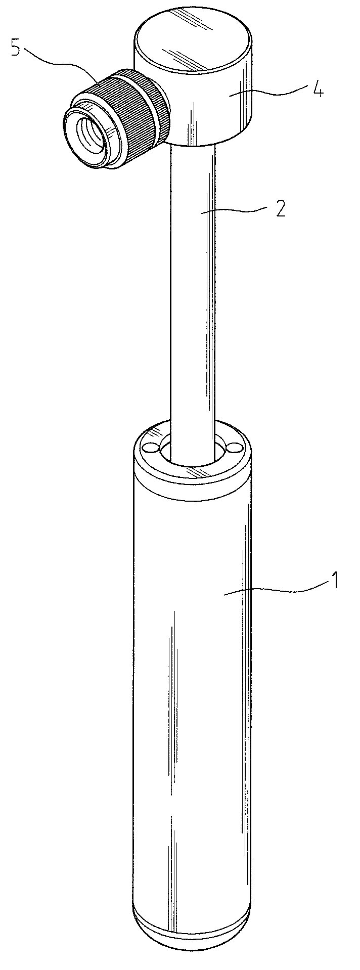
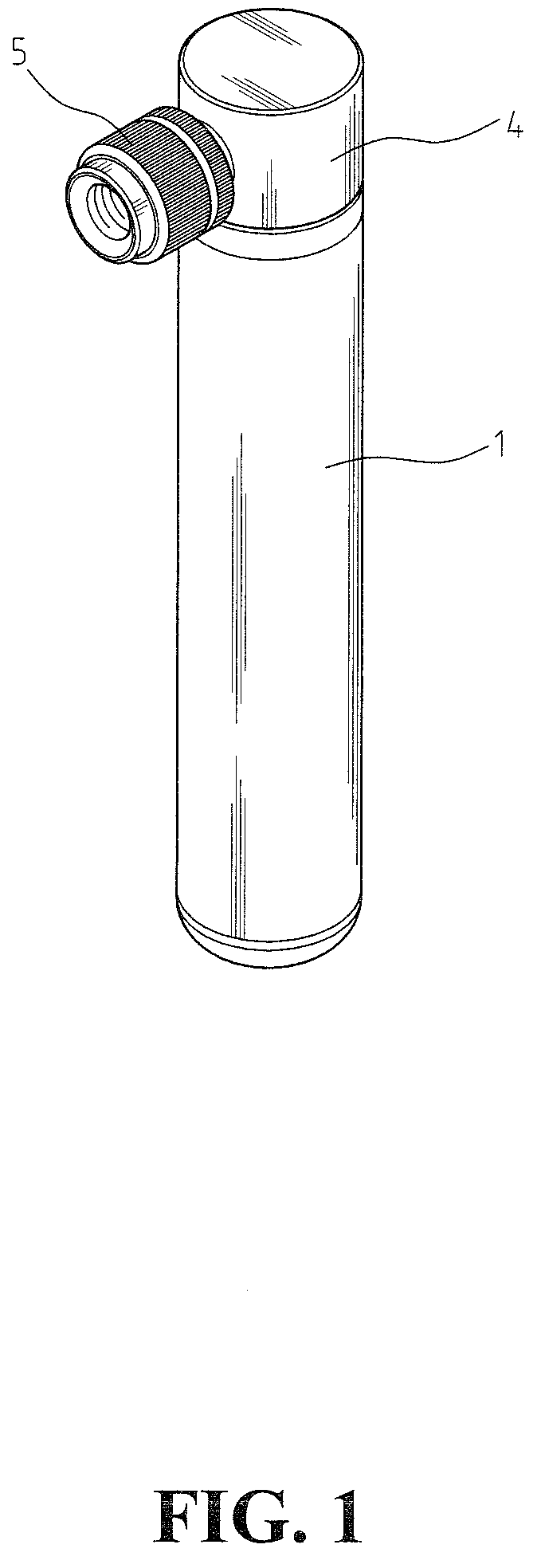
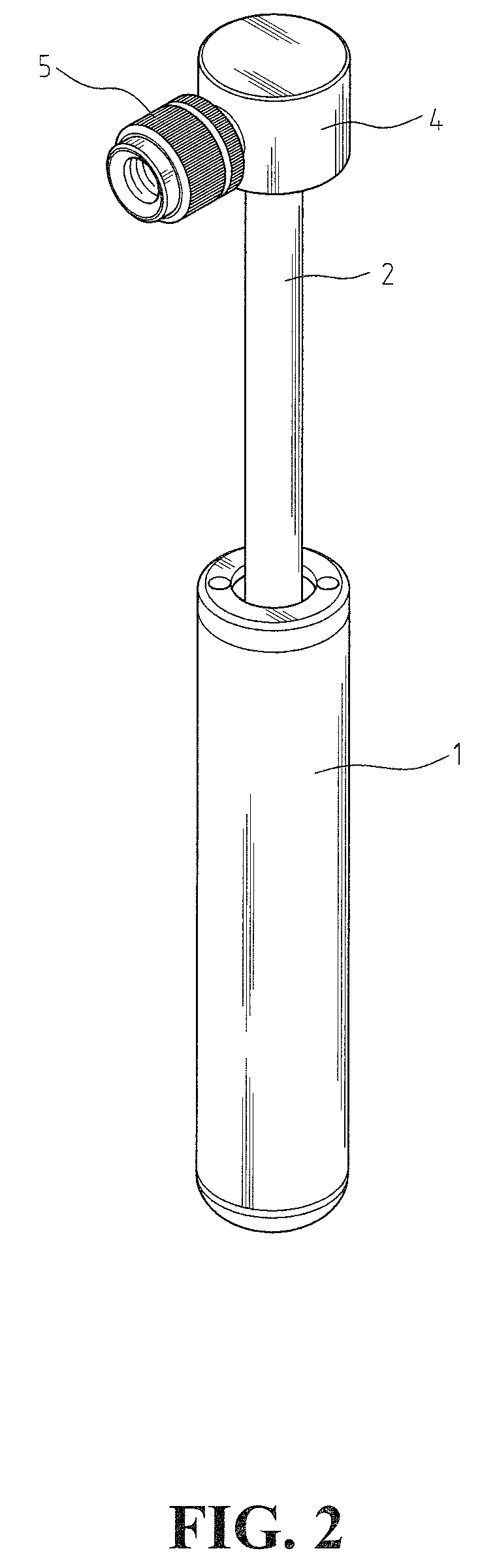
[0022]FIG. 1 and FIG. 2 are a plurality of perspective views showing a portable air pump according to an embodiment of the present invention, which includes a tubular body 1, a barrel 2 penetrating through the tubular body 1, a head 4 disposed on the barrel 2, and a dispensing head 5 disposed to the head 4. The barrel 2 and the tubular body 1 can move relative to one another along the axis direction, so that the air can be pushed out through the head 4 and the dispensing head 5.

[0023]FIG. 3 and FIGS. 4A-4B are a plurality of schematic diagrams illustrating a preferred embodiment according to the present invention, which show the method of assem...


PUM


Abstract

A portable air pump includes a tubular body, a barrel, a piston mechanism, a head, and a dispensing head. Tubular body has upper cover having air inlet holes and sealed bottom cover. Barrel has air passage running through along its axis direction. Piston, having center hole and through hole, and check valve is in between second end of the barrel and piston. As tubular body is moved in relation to barrel away from the head, air is flown into tubular body through air inlet holes and to the bottom of tubular body through the through hole. Air can be prevented from flowing out from the center hole using check valve disc. As the tubular body is moved in relation to the barrel towards the head, air on the bottom of tubular body is flown into air passage of the barrel through center hole, and out from the head and the dispensing head.

Description

BACKGROUND OF THE INVENTION[0001]1. Field of the Invention[0002]The present invention relates to an air pump for inflating air-inflatable objects (such as a tire), and in particular, to an air pump having advantages such as occupying a smaller volume and is portable.[0003]2. The Prior Arts[0004]Generally, the conventional air pump mainly includes an inflating pump, a head for connecting with the inflating pump, and a dispensing head, in which one end is connected with the head. After the other end of the dispensing head is connected with an air valve of the inflated object, the inflating pump can be operated so as to produce compressed air, and then the air can be inflated into the inflated object through the head and an air hose.[0005]For the sake of allowing for easier carrying portability, several air pumps have been designed to occupy a smaller volume, such as a conventional air pump as shown in FIG. 6, which includes a tubular body A, a handle B, a head C, a nosepiece D which i...

Claims


Application Information

Patent Timeline
IPC IPC(8): F04B53/00
CPCF04B33/005
Inventor HUANG, YING-CHE
Owner HUANG YING CHE
Why Eureka
Try Eureka