Electric Power Flow Control

a technology of electric power flow and control circuit, applied in the direction of automatic control, process and machine control, instruments, etc., can solve the problems of increasing the need for maintenance, pst cannot participate in a decisive way, and the use of pst however offers a slow control speed

Inactive Publication Date: 2008-10-23
ABB RES LTD
View PDF11 Cites 18 Cited by
  • Summary
  • Abstract
  • Description
  • Claims
  • Application Information

AI Technical Summary

Benefits of technology

[0009]A primary object of the present invention is to provide a power flow control of an ac power transmission that is rapid and that does not involve the drawbacks of the single use of either a PST or a SSSC.
[0014]The PST which is regulated in sequential steps by the tap changer is according to the invention combined with a SSSC which is regulated by a VSC, to provide a fast and adaptive control of the power flow by a common control system. The slow control capability of the PST is compensated for by the rapid control of the VSC. The PST is thus dynamically supported by the VSC of the SSSC when regulating. This dynamically supported PST, in the following text denoted DSPST, comprises a standard tap changer controlled PST combined with a SSSC containing a controllable VSC. The dynamic assistance of the PST reduces the number of control actions made by the tap changer, which dramatically increases the life time cycle of the tap changer.

Problems solved by technology

The use of a PST however offers a slow control speed.
Thus the PST cannot participate in a decisive way in a transient period following a power disturbance.
Further frequent tap changing, in particular at high current conditions, increases the need for maintenance.
The tap changer is a mechanical device and thus slow in operation and an object to mechanical wear.
However, the SSSC has a larger variation in reactive power production / consumption than the PST.
Furthermore the SSSC is expensive compared to the PST.

Method used


Image

  • Electric Power Flow Control
  • Electric Power Flow Control
  • Electric Power Flow Control

Examples


Embodiment Construction

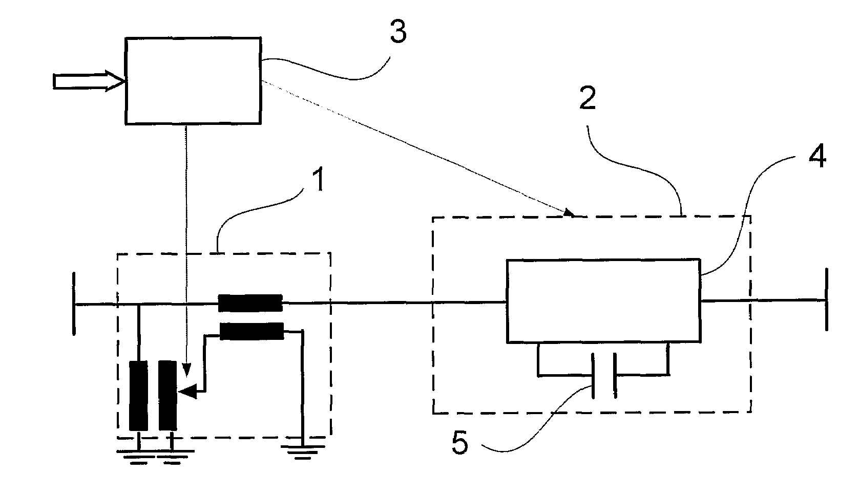
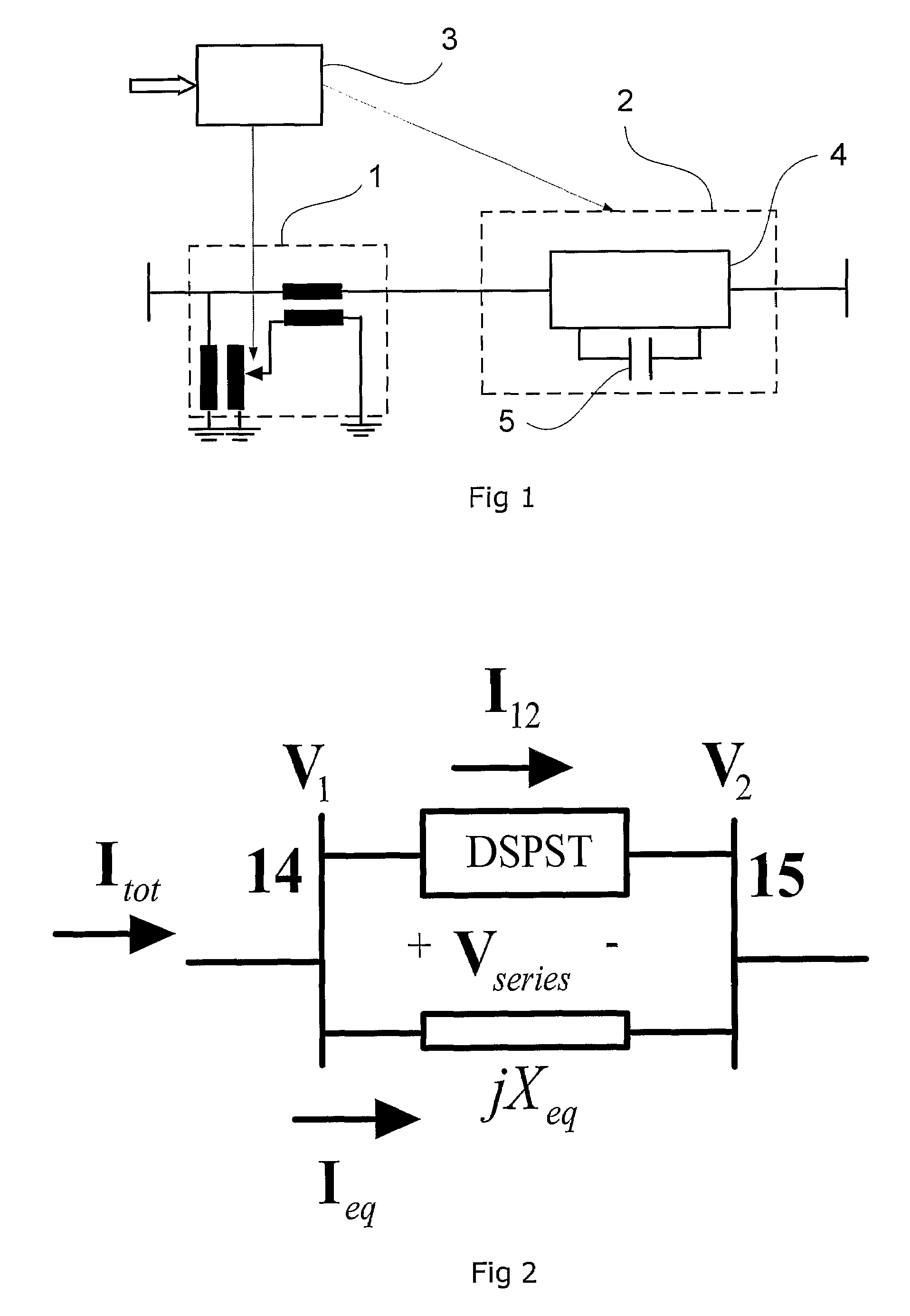
[0027]An apparatus for controlling the power flow according to the invention is shown in FIG. 1. The apparatus comprises a tap changer controlled phase shifting transformer (PST) 1, a controlled Static Synchronous Series Compensator (SSSC) 2 and a control unit 3. The SSSC comprises a Voltage Source Converter (VSC) 4 and a DC-capacitor 5. The DC capacitor comprises in one embodiment a plurality of capacitor units. The VSC comprises a two level bridge containing a plurality of series connected switching devices. Each switching device comprises a semiconducting element with a diode connected in antiparallel therewith. The converter topology is similar to that of a STATCOM and known from the literature. In one embodiment the VSC is connected to the AC line potential directly. In another embodiment the VSC is connected to the line by means of a series transformer.

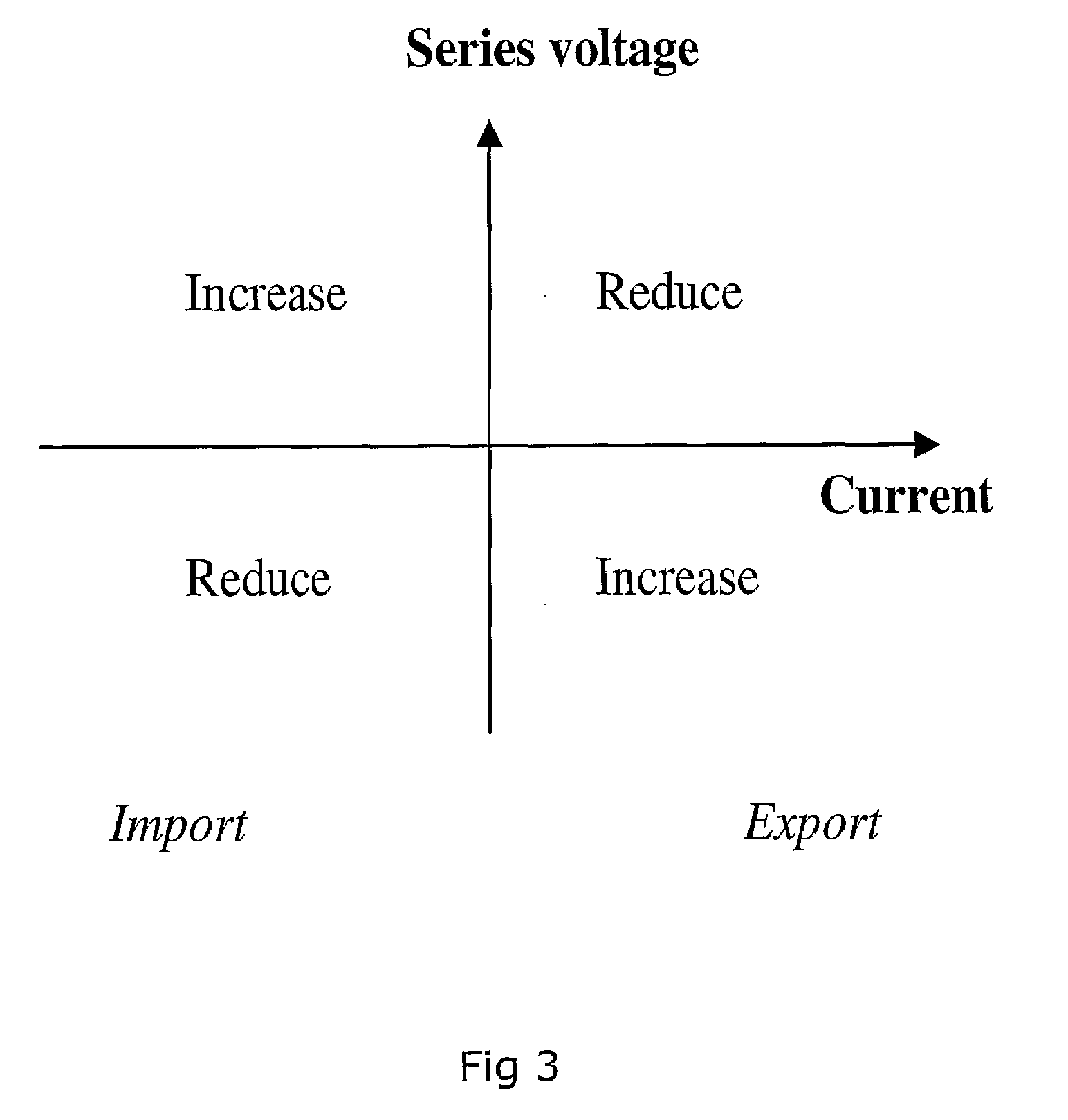
[0028]The SSSC injects a continuously variable series compensating voltage in quadrature with the line current, i.e. either le...


PUM


Abstract

An apparatus for controlling power flow in a high voltage network. A phase shifting transformer includes a tap changer.

Description

TECHNICAL FIELD[0001]The present invention concerns an apparatus and a method for controlling the power flow in an ac transmission system. More precisely the invention concerns a control apparatus comprising a phase shifting transformer (PST). By a phase shifting transformer should in this context be understood to include a single cored as well as a multiple cored transformer, both of which may comprise a symmetric or an asymmetric design. The phase shifting transformer may also comprise additional voltage regulating means.BACKGROUND OF THE INVENTION[0002]A phase shifting transformer is previously known for controlling the power flow in an ac transmission line. Such PST comprises a tap changer that serially connects or disconnects additional windings of the transformer. By doing so the phasor orientation is controlled. Power is then moved from adjacent phases to a single phase by connections between windings excited by different parts of the magnetic circuit. In a pure phase shiftin...

Claims


Application Information

Patent Timeline
Patent Type & Authority Applications(United States)
IPC IPC(8): H02J3/00
CPCH02J3/06H02J3/1814Y02E40/18Y02E40/10Y02E40/30H02J3/1878
Inventor BERGGREN, BERTILNOROOZIAN, MOJTABA
Owner ABB RES LTD
Why Eureka
Try Eureka