Electric Power Flow Control

a technology of electric power flow and control circuit, applied in the direction of automatic control, process and machine control, instruments, etc., can solve the problems of increasing the need for maintenance, pst cannot participate in a decisive way, and the use of pst however offers a slow control speed

Inactive Publication Date: 2008-07-03
ABB POWER GRIDS SWITZERLAND AG +1
View PDF11 Cites 17 Cited by
  • Summary
  • Abstract
  • Description
  • Claims
  • Application Information

AI Technical Summary

Benefits of technology

[0011]A primary object of the present invention is to provide a power flow control of an ac power tra...

Problems solved by technology

The use of a PST however offers a slow control speed.
Thus the PST cannot participate in a decisive way in a transient period following a power disturbance.
Further frequent tap changing, in particular at high current conditions...

Method used


Image

  • Electric Power Flow Control
  • Electric Power Flow Control
  • Electric Power Flow Control

Examples


Embodiment Construction

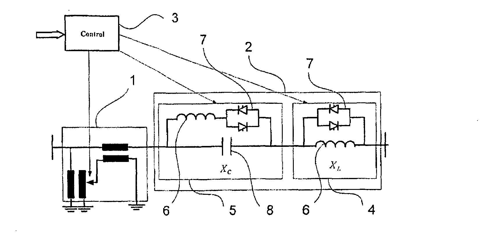
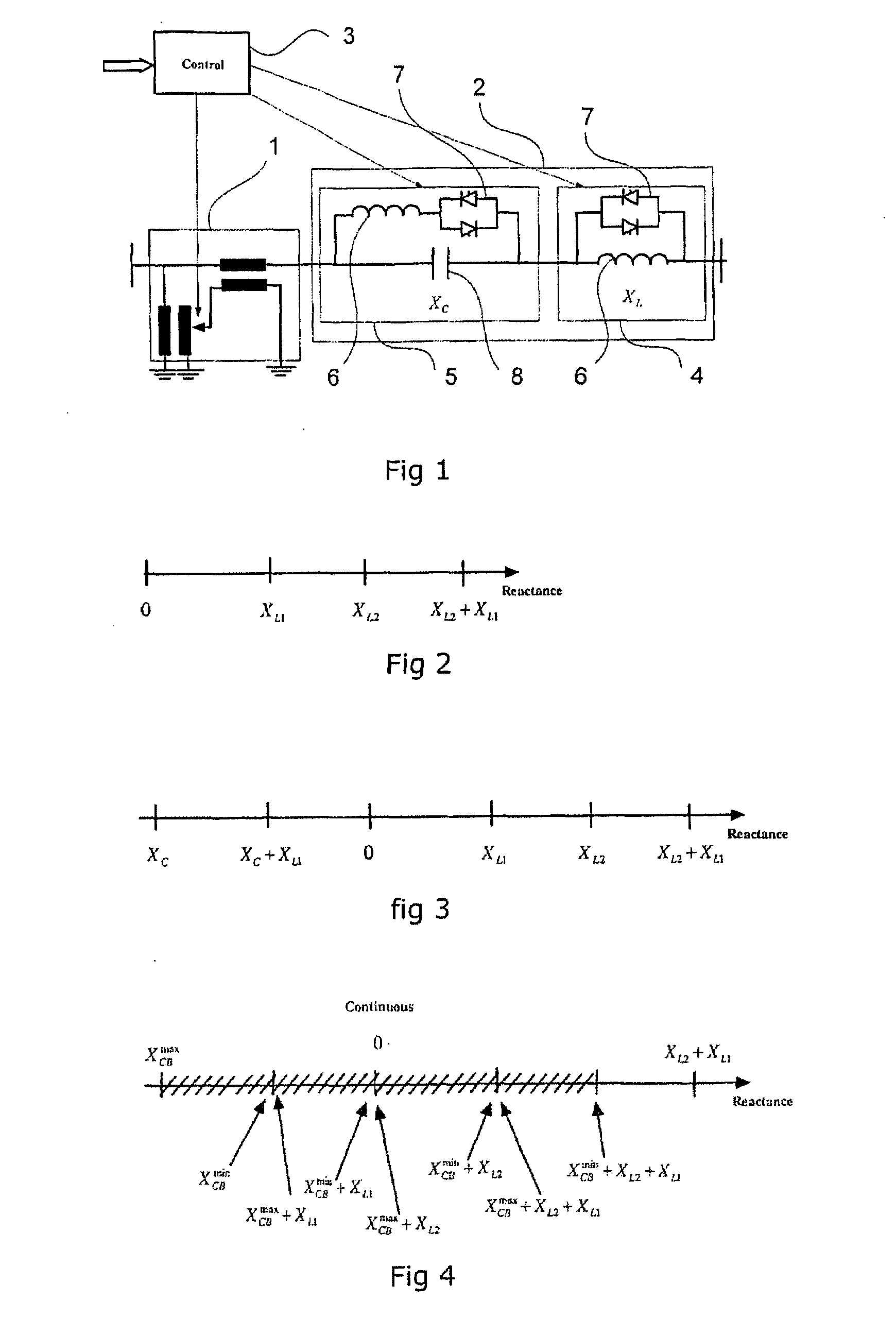
[0033]An apparatus for controlling the power flow according to the invention is shown in FIG. 1. The apparatus comprises a tap changer controlled phase shifting transformer (PST) 1, a controlled series compensator (CSC) 2 and a control unit 3. The CSC comprises a first reactance unit 4 that includes an inductive unit 6 and a thyristor switch 7 for connecting and disconnecting the inductive unit. In the embodiment shown the CSC 2 also comprises a second reactance unit 5 that includes a capacitive unit 8 as well as a inductive unit 6 that are controlled by a thyristor switch 7. The single inductive and capacitive reactance units are shown by way of example. It lies within the scope of the invention to combine any number of inductive and capacitive steps. Thus the controlled series compensation device may comprise a plurality of both inductive and capacitive circuits.

[0034]The CSC may be realized in different configurations. In a first embodiment the CSC comprises switchable inductive ...


PUM


Abstract

An apparatus for controlling the power flow in a high voltage network. A phase shifting transformer includes a tap changer.

Description

TECHNICAL FIELD[0001]The present invention concerns an apparatus and a method for controlling the power flow in an ac transmission system. More precisely the invention concerns a control apparatus comprising a phase shifting transformer (PST). By a phase shifting transformer should in this context be understood to include a single cored as well as a multiple cored transformer, both of which may comprise a symmetric or an asymmetric design. The phase shifting transformer may also comprise additional voltage regulating means.BACKGROUND OF THE INVENTION[0002]A phase shifting transformer is previously known for controlling the power flow in an ac transmission line. Such PST comprises a tap changer that serially connect or disconnect additional windings of the transformer. By doing so the phasor orientation is controlled. Power is then moved from adjacent phases to a single phase by connections between windings excited by different parts of the magnetic circuit. In a pure phase shifting ...

Claims


Application Information

Patent Timeline
IPC IPC(8): H01F27/42
CPCH02J3/1807Y02E40/30Y02E40/10H02J3/1878
Inventor BERGGREN, BERTILNOROOZIAN, MOJTABA
Owner ABB POWER GRIDS SWITZERLAND AG
Why Eureka
Try Eureka